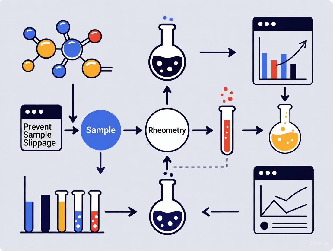
Preventing Wall Slip in Rheometry: A Complete Guide for Accurate Biomaterial Characterization
Wall slip is a pervasive challenge in rheological testing of complex fluids like concentrated emulsions, suspensions, and polymer melts, often leading to significant underestimation of key parameters such as yield...
Preventing Wall Slip in Rheometry: A Complete Guide for Accurate Biomaterial Characterization
Abstract
Wall slip is a pervasive challenge in rheological testing of complex fluids like concentrated emulsions, suspensions, and polymer melts, often leading to significant underestimation of key parameters such as yield stress and viscosity. This article provides a comprehensive, evidence-based guide for researchers and drug development professionals on understanding, preventing, and correcting for wall slip artifacts. Covering foundational theories, practical mitigation strategies using roughened geometries and vane rotors, advanced troubleshooting protocols, and validation techniques, this resource equips scientists with the methodologies needed to ensure data integrity in the rheological characterization of pharmaceuticals, biologics, and other advanced biomaterials.
Understanding Wall Slip: Causes, Mechanisms, and Impact on Rheological Data
Wall slip is a common phenomenon in rheometry that occurs when a thin, low-viscosity layer forms at the interface between a sample and the measuring geometry of a rheometer. This creates a lubrication effect that causes the sample to "slip" at the wall rather than deforming uniformly [1]. For researchers and scientists in drug development and material science, wall slip presents a significant challenge as it leads to inaccurate rheological data, particularly the underestimation of key parameters like viscosity and yield stress [1] [2]. This technical guide provides comprehensive troubleshooting resources to help you identify, mitigate, and quantify wall slip in your experiments.
Frequently Asked Questions (FAQs)
What is wall slip and why does it occur in rheological measurements?
Wall slip refers to the formation of a thin low-viscosity boundary layer at the interface between a sample and the geometry wall during rheological testing. This phenomenon typically arises from static, hydrodynamic, viscoelastic, chemical, and gravitational forces acting on a dispersed phase immediately adjacent to solid boundaries [1]. In practical terms, it occurs when particles in suspensions or droplets in emulsions migrate away from geometry walls, creating a lubricating layer that facilitates slip [2].
Which types of materials are most susceptible to wall slip?
Wall slip most commonly affects materials with heterogeneous structures, including:
- Highly concentrated dispersions and suspensions (e.g., toothpaste, ceramic slurries) [1]
- Concentrated emulsions (e.g., lotions, creams) [1]
- Polymer melts, especially those with high molecular weight and narrow molecular weight distribution [3]
- Fresh cement-based materials [4]
- Particulate slurries and fluid muds [5]
What are the telltale signs that wall slip is affecting my measurements?
Several indicators can suggest wall slip is occurring in your experiments:
- Apparent viscosity measurements that decrease with decreasing geometry size [1]
- Anomalous "dog leg" shapes in flow curves [2]
- Yield stress values that are significantly lower than expected [1]
- Measurement results that vary depending on the gap size used in parallel plate geometries [2]
- Discontinuities in flow curves, particularly for polymer melts [3]
What are the most effective strategies to prevent or minimize wall slip?
Multiple effective approaches exist to counter wall slip:
Table: Strategies for Preventing Wall Slip
| Strategy | Mechanism | Applications |
|---|---|---|
| Roughened/Serrated Geometries | Creates physical barriers that penetrate slip layer, enhancing sample-sample contact [1] | Parallel plate and cone-plate systems |
| Crosshatched Surfaces | Provides irregular surface to break through depletion layer [1] | Concentrated dispersions and emulsions |
| Vane Rotors | Eliminates wall slip by moving shearing surface away from wall interface [1] [5] | Yield stress measurements in suspensions |
| Ribbed Containers | Reduces boundary slippage through surface patterning [4] | Coaxial cylinder measurements |
| Sandblasted Surfaces | Increases surface roughness to improve grip [3] | Various rheological applications |
Troubleshooting Guides
How to Diagnose Wall Slip
Objective: Confirm the presence and magnitude of wall slip in your measurements.
Materials Needed: Rheometer, smooth parallel plates or concentric cylinders, sample material.
Protocol:
- Gap Variation Method:
- Geometry Comparison:
- Perform identical tests using both smooth and serrated/roughened geometries
- Significant differences in measured values (especially yield stress) indicate slip [1]
Diagram: Wall Slip Diagnosis Workflow
How to Eliminate Wall Slip in Concentrated Dispersions and Emulsions
Objective: Obtain accurate rheological measurements for concentrated dispersions and emulsions by eliminating wall slip effects.
Experimental Background: Highly concentrated dispersions like toothpaste and emulsions like hand cream consistently demonstrate wall slip effects, particularly in yield stress measurements. One study showed yield stress measurements for toothpaste were more than 5 times higher when using slip-prevention geometries compared to smooth plates [1].
Protocol:
- Geometry Selection:
Sample Loading:
- Load sample carefully to prevent premature disruption of structure
- Allow appropriate temperature equilibration before testing
Testing Parameters:
- Conduct steady state flow experiments from low torque to beyond yield stress
- Perform oscillation stress/strain sweeps to determine linear viscoelastic region
Table: Effectiveness of Different Geometries for Yield Stress Measurement
| Geometry Type | Toothpaste Yield Stress (Pa) | Hand Lotion Yield Stress (Pa) | Effectiveness |
|---|---|---|---|
| Smooth Plates | 18.1 | 60.6 | Poor - Significant slip |
| Bottom Crosshatched Only | 21.7 | 76.4 | Moderate |
| Top Crosshatched Only | 32.2 | 76.6 | Moderate |
| Both Plates Crosshatched | 105.2 | 175.0 | Excellent - Minimal slip [1] |
How to Quantify Wall Slip Velocity in Polymer Melts
Objective: Measure the wall slip velocity of polymer melts using the Mooney method.
Experimental Background: In capillary rheometry, wall slip becomes significant when wall shear stress exceeds a critical value, potentially causing extrudate distortion ranging from loss of gloss to gross melt fracture [3]. The Mooney method allows quantification of this slip velocity.
Protocol:
- Die Selection:
Testing Procedure:
- Conduct flow curve measurements for each die at constant temperature
- Cover appropriate shear rate range (e.g., 10-290 1/s for LLDPE at 190°C) [3]
Data Analysis:
- At constant shear stress, plot apparent shear rate against inverse die radius (1/R)
- The slope of this Mooney plot equals 4V~s~, where V~s~ is the slip velocity [3]
- Repeat for multiple shear stress values to create slip velocity vs. shear stress relationship
Diagram: Mooney Method for Slip Velocity Quantification
The Scientist's Toolkit: Essential Research Reagents and Materials
Table: Key Materials for Wall Slip Prevention and Analysis
| Material/Geometry | Function | Application Context |
|---|---|---|
| Serrated Parallel Plates | Disrupts slip layer through physical intrusion | Concentrated dispersions, yield stress measurements [1] [2] |
| Crosshatched Geometries | Enhances sample-sample contact at wall interface | Emulsions, suspensions, pastes [1] |
| Vane Rotor | Eliminates wall contact at shearing surface | Yield stress fluids, fragile structures [1] [5] |
| Ribbed Containers | Reduces boundary slippage in coaxial systems | Cement-based materials, pastes [4] |
| Capillary Dies (Various Sizes) | Enables Mooney method for slip quantification | Polymer melts, extrusion studies [3] |
| Rough Surface Geometries | Increases friction between sample and geometry | General rheometry of slip-prone materials [4] |
Frequently Asked Questions (FAQs) on Wall Slip
FAQ 1: What is wall slip and why is it a problem in rheometry? Wall slip is a common phenomenon where a thin, low-viscosity layer forms at the interface between a sample and the geometry surface of a rheometer. This occurs due to particle depletion, wettability issues, or shear-induced migration in concentrated dispersions or emulsions. This layer acts as a lubricant, causing the sample to "slip" at the wall rather than experiencing the true shear rate. The primary problem is that it leads to significantly underestimated viscosity and yield stress measurements, potentially invalidating experimental data [1].
FAQ 2: For which types of samples is wall slip a major concern? Wall slip is particularly problematic for materials with a dispersed phase, including [1]:
- Highly concentrated emulsions (e.g., hand lotions).
- Suspensions and pastes (e.g., toothpaste).
- Samples containing large or flocculated particles.
- Concentrated solutions of high molecular weight polymers.
- Materials containing oil or fat [6].
FAQ 3: How can I experimentally confirm that wall slip is affecting my measurements? A classic method for identifying wall slip is to perform identical flow tests using measuring geometries of the same type but with different gap sizes. If the measured apparent viscosity decreases with a decreasing gap size, it is a strong indicator that wall slip is occurring [1].
FAQ 4: What are the most effective solutions to prevent wall slip? The most effective strategies involve physically or chemically altering the interface between the sample and the geometry to prevent slip [1] [6]:
- Using roughened surfaces: Replace standard smooth plates with crosshatched or serrated geometries.
- Employing a vane geometry: Using a vane-shaped rotor inside a grooved cup is considered one of the best solutions for eliminating wall slip.
- Ensuring correct gap setting: As a rule of thumb, the measuring gap should be at least 10 times larger than the maximum particle or agglomerate size in your sample [6].
Troubleshooting Guide: Identifying and Resolving Wall Slip
Step 1: Symptom Identification
Check if your data exhibits these common signs of wall slip:
- Artificially low viscosity: Measured values are lower than expected.
- Yield stress underestimation: Yield stress values are unrealistically low and not reproducible.
- Geometry-dependent results: Viscosity changes when using different gap sizes or geometry diameters.
- Fluctuating data: Significant noise or continuous decrease in measured values during a test.
Step 2: Root Cause Analysis
Refer to the following table to diagnose the primary cause of slip in your experiment.
| Primary Cause | Underlying Mechanism | Common Sample Types |
|---|---|---|
| Particle Depletion | Osmotic or gravitational forces cause particles to migrate away from the geometry wall, creating a thin, particle-depleted, low-viscosity layer [1]. | Concentrated dispersions (e.g., toothpaste), suspensions with large or flocculated particles [1]. |
| Wettability Issues | Poor adhesion between the sample and the geometry surface due to incompatible surface energies, leading to lubrication at the wall [6]. | Oily or fatty samples, low surface tension liquids, hydrophobic materials on hydrophilic geometries (or vice versa) [6]. |
| Shear-Induced Transitions | High shear rates or stresses can induce migration of the dispersed phase, creating a localized slip layer or even causing structural failure at the edge of the geometry [6]. | Highly viscous and viscoelastic samples (e.g., polymer melts, pastes) at high shear rates [6]. |
Step 3: Implementation of Corrective Actions
Based on the diagnosed root cause, apply the solutions below.
| Corrective Action | Implementation Details | Primary Cause Addressed |
|---|---|---|
| Use Roughened Geometries | Replace smooth parallel plates or cone/plate with crosshatched, serrated, or sandblasted surfaces. The rough texture breaks through the slip layer and improves grip [1] [6]. | All, but particularly effective for Particle Depletion and Wettability. |
| Utilize Vane & Cup Geometry | Use a vane rotor, which shears the sample within its own body, completely avoiding wall slip at the rotor interface. A grooved inner cup can further prevent slip at the outer boundary [1]. | All, especially for fragile gels and pastes. |
| Optimize Measuring Gap | Ensure the gap is at least 10x larger than the largest particle or agglomerate in the sample to minimize wall effects [6]. | Particle Depletion. |
| Verify Gap Setting & Sample Loading | Perform a correct zero-gap setting with modern rheometer software. Avoid overfilling or underfilling the geometry, as both can lead to erroneous data [6]. | All (General Best Practice). |
| Control Shear Rate / Stress | For shear-induced effects, reduce the maximum shear rate/stress or use a shorter measurement duration to minimize sample ejection (edge failure) or viscous heating [6]. | Shear-Induced Transitions. |
Experimental Data & Protocols
Quantitative Impact of Wall Slip and Its Mitigation
The following table summarizes experimental data demonstrating how wall slip drastically reduces measured yield stress and how corrective geometries restore accurate values.
| Sample | Measuring Geometry | Measured Yield Stress (Pa) | Notes & Improvement |
|---|---|---|---|
| Toothpaste | Smooth Plates | 18.1 Pa | Reference (erroneous) value due to severe wall slip [1]. |
| (Concentrated Dispersion) | One Crosshatched Plate | 21.7 - 32.2 Pa | Partial improvement, but slip still occurs on the smooth side [1]. |
| Both Plates Crosshatched | 105.2 Pa | >5x increase vs. smooth plates; considered the true material yield stress [1]. | |
| Hand Lotion | Smooth Plates | 60.6 Pa | Reference (erroneous) value, ~65% lower than true value [1]. |
| (Concentrated Emulsion) | One Crosshatched Plate | ~76.5 Pa | Partial improvement [1]. |
| Both Plates Crosshatched | 175.0 Pa | True yield stress, effectively eliminating slip [1]. |
Detailed Protocol: Yield Stress Measurement with Slip Elimination
This protocol describes a standardized method for accurately determining the yield stress of a concentrated dispersion while mitigating wall slip effects.
I. Objective: To measure the steady-state yield stress of a concentrated dispersion (e.g., toothpaste) using a rotational rheometer equipped with geometries that prevent wall slip.
II. Materials & Equipment:
- Rheometer with temperature control (e.g., Peltier plate).
- Crosshatched parallel plate geometries (recommended diameter: 25-40 mm).
- Sample (e.g., toothpaste).
- Spatula for loading.
III. Procedure:
- Temperature Equilibration: Turn on the rheometer and set the Peltier plate to the desired test temperature (e.g., 25 °C). Allow the instrument to equilibrate for at least 10 minutes [6].
- Geometry Setup: Install the crosshatched lower plate. In the rheometer software, perform a zero-gap calibration for the chosen geometry.
- Sample Loading: Using a spatula, place a sufficient but controlled amount of sample onto the center of the lower plate. Avoid incorporating air bubbles.
- Gap Setting: Move the upper geometry (also crosshatched) to the desired measuring gap. The gap should be at least 10 times the largest particle size in the sample. Carefully trim excess sample from the geometry edge with a spatula.
- Sample Resting: Allow the sample to rest for a defined period (e.g., 5 minutes) to enable structural recovery and temperature equilibration, minimizing thixotropic effects [6].
- Test Programming: Program a steady-state flow test with a linear or logarithmic ramp of shear stress from a low value to a point beyond the expected yield stress.
- Execution: Start the measurement. Monitor the viscosity or shear stress curve for a sharp decrease, which indicates yielding.
- Data Analysis: Identify the yield stress as the peak stress value just before the sharp drop in viscosity or as the stress value at a defined offset in viscosity.
Visual Workflows
Wall Slip Troubleshooting Logic
Slip-Corrected Yield Stress Measurement
The Scientist's Toolkit: Research Reagent Solutions
This table details key materials and tools used to prevent and diagnose wall slip in rheological experiments.
| Item | Function & Rationale |
|---|---|
| Crosshatched/Serrated Parallel Plates | Roughened surface geometries that penetrate the low-viscosity slip layer, providing better grip on the sample and forcing deformation within the bulk material [1]. |
| Vane Rotor with Cup | A multi-bladed vane shears the sample within its own structure, eliminating slip at the rotor interface. A matched cup with a grooved inner surface prevents slip at the container wall [1]. |
| Sandblasted Concentric Cylinders (Cup & Bob) | Provides a roughened surface for samples tested in a concentric cylinder geometry, suitable for lower-viscosity liquids that might flow out of parallel plate gaps [6]. |
| Dummy Test Chips | (For microfluidic rheometers) Allows for testing and optimization of cleaning protocols or checking for particle blockages without risking damage to the actual, more expensive sensor chip [7]. |
| High-Performance Computing (HPC) & Modeling Software | Software like MedeA or Materials Studio enables multiscale modeling of material behavior, which can help predict conditions (e.g., shear rates, particle concentrations) that may lead to slip phenomena [8]. |
Troubleshooting Guides & FAQs
Frequently Asked Questions
Q1: What is wall slip and why is it a problem in rheometry? Wall slip is a common phenomenon where a thin, low-viscosity layer forms at the boundary between the sample and the geometry of the rheometer. This layer acts as a lubricant, causing the sample to "slip" rather than undergoing true, homogeneous deformation. It leads to significantly underestimated values for key material properties like viscosity and yield stress, as the measured resistance to flow is artificially low [1].
Q2: Which types of materials are most prone to wall slip? Wall slip is frequently encountered when testing materials that have a dispersed phase. Common problematic materials include [1] [6]:
- Concentrated dispersions and suspensions (e.g., toothpaste, ceramic slurries)
- Highly concentrated emulsions (e.g., lotions, creams, sauces)
- Polymer melts filled with particles
- Pastes and other soft solids
Q3: My sample is slipping. How can I confirm this is the issue? A strong indicator of wall slip is a dependence of your measured apparent viscosity on the geometry size or gap. If you perform the same test using geometries with different diameters (for parallel plates) or gaps, and you observe a decrease in measured viscosity with a smaller geometry or gap, wall slip is likely influencing your results [1]. Another tell-tale sign is a sudden, continuous drop in the viscosity curve during a shear rate sweep [9].
Q4: What are the best solutions to prevent wall slip? The most effective solutions involve physically altering the interface between the sample and the geometry to enhance grip. The primary methods are [1] [6] [9]:
- Use Geometries with Roughened Surfaces: Replace standard smooth plates or cylinders with ones that have sandblasted, serrated, or crosshatched surfaces.
- Employ a Vane Geometry: For delicate structures or yield stress measurements, a vane rotor inside a grooved cup can slice into the sample without disturbance and is exceptionally effective at eliminating slip.
- Ensure Adequate Gap Size: As a rule of thumb, the measuring gap should be at least 10 times larger than the largest particle in your sample to prevent jamming and artifacts [6] [9].
Troubleshooting Guide: Identifying and Correcting Wall Slip
| Problem Symptom | Likely Cause | Recommended Solution | Key Considerations |
|---|---|---|---|
| Measured viscosity decreases with smaller geometry gap [1] | Wall slip | Switch to serrated or crosshatched parallel plates [1]. | Ensure gap is still >10x largest particle size [9]. |
| Viscosity curve shows sudden, continuous drop [9] | Wall slip in suspensions/emulsions | Use a roughened surface cup and bob or a vane geometry [1] [9]. | A vane geometry is ideal for fragile structures like gels and foams [9]. |
| Low-viscosity sample results in fluctuating data at high frequencies | Fluid inertia & shear waves [6] | Use a large-diameter cone/plate (e.g., 50 mm) with a very small cone angle (e.g., 0.5°-1°) [6]. | Minimizes the sample volume and reduces the effect of wave propagation. |
| Sample is ejected from the gap at high shear rates | Centrifugal force or edge fracture [6] | Shorten measurement duration; use a solvent trap to prevent evaporation [6]. | For polymer melts, edge fracture is a sign of exceeding the material's elastic limit. |
| Erratic data with highly filled/pigmented systems | Particle jamming in narrow gaps [9] | Use parallel plates with a large, adjustable gap or concentric cylinder geometries [9]. | Concentric cylinders (cup and bobs) accommodate larger particles more easily [9]. |
Quantitative Impact of Wall Slip Mitigation
The following table summarizes experimental data demonstrating how corrective geometries significantly improve the accuracy of yield stress measurements in concentrated dispersions and emulsions. The data clearly shows that using roughened surfaces on both the top and bottom plates (TBCH) provides the most accurate results [1].
Table: Influence of Geometry Surface on Measured Yield Stress [1]
| Sample | Geometry Type (Surface) | Abbreviation | Measured Yield Stress (Pa) |
|---|---|---|---|
| Toothpaste (Concentrated Dispersion) | Smooth Plates | SP | 18.1 |
| Bottom Crosshatched / Top Smooth | BCH | 21.7 | |
| Top Crosshatched / Bottom Smooth | TCH | 32.2 | |
| Both Plates Crosshatched | TBCH | 105.2 | |
| Hand Lotion (Concentrated Emulsion) | Smooth Plates | SP | 60.6 |
| Bottom Crosshatched / Top Smooth | BCH | 76.4 | |
| Top Crosshatched / Bottom Smooth | TCH | 76.6 | |
| Both Plates Crosshatched | TBCH | 175.0 |
Experimental Protocol: Yield Stress Measurement with Wall Slip Mitigation
This protocol is adapted from application notes for testing concentrated dispersions and emulsions [1].
1. Objective: To accurately determine the yield stress of a concentrated dispersion or emulsion while minimizing the effects of wall slip.
2. Materials and Equipment:
- Rotational rheometer with temperature control (e.g., Peltier plate).
- Preferred: Crosshatched or serrated parallel plate geometries (recommended diameter: 20-40 mm for high-viscosity samples).
- Alternative: Standard smooth parallel plates (for comparison) or a vane and cup geometry.
- Sample (e.g., toothpaste, hand cream).
3. Methodology:
- Temperature Equilibration: Set and maintain the rheometer temperature at 25 °C. Allow the geometry and sample to equilibrate for at least 5-10 minutes after loading [6].
- Gap Setting: For parallel plates, set the measuring gap to 1.0 mm (or ensure it is at least 10 times the size of the largest particle in the sample) [6] [9].
- Sample Loading: Carefully load the sample onto the center of the bottom plate, avoiding air bubble incorporation.
- Test Programming: Program a steady-state flow test.
- Mode: Controlled shear stress or controlled shear rate.
- Ramp: A slow, linear ramp from low stress/rate to a point beyond the expected yield stress.
- Temperature: 25 °C.
- Data Analysis: The yield stress is identified as the point where the shear rate shows a significant increase or the viscosity drops precipitously, indicating the material has begun to flow.
4. Key Considerations:
- Comparison: For a comprehensive study, compare results from smooth plates versus roughened plates to visualize the impact of wall slip.
- Sample History: Ensure consistent sample preparation and loading to achieve reproducible results [6].
The Scientist's Toolkit: Essential Research Reagents & Materials
Table: Key Tools for Reliable Rheometry of Problematic Materials
| Item | Function | Application Notes |
|---|---|---|
| Serrated/Crosshatched Plates | Prevents wall slip by physically gripping the sample and breaking through the low-viscosity layer [1]. | Ideal for concentrated dispersions, pastes, and emulsions. Use on both top and bottom for maximum effect [1]. |
| Sandblasted (Roughened) Geometries | Provides a microscopically rough surface to enhance adhesion and reduce slip [6] [9]. | A good general-purpose solution for samples showing moderate slip, such as those containing oils or fats [6]. |
| Vane Rotor & Cup | Eliminates wall slip by having a large surface area that moves through the sample without disturbing its structure; the cup often has a grooved inner surface [1] [9]. | The gold standard for measuring yield stress in delicate structures (yogurt, gels) and for highly slippery samples [9]. |
| Concentric Cylinders (Cup & Bob) | Minimizes evaporation and is less prone to edge effects. A large gap can accommodate particles [6] [9]. | Recommended for low-viscosity liquids and samples that sediment. Roughened or splined surfaces are available for slippery samples [9]. |
| PEEK (Polyether Ether Ketone) Geometries | Chemically resistant polymer geometry for corrosive or acidic samples [9]. | Prevents reaction between the sample and metal geometries, ensuring material integrity and measurement accuracy. |
Experimental Workflow for Wall Slip Mitigation
The following diagram outlines a systematic decision-making process for selecting the appropriate rheometer geometry to prevent wall slip, based on sample properties.
Diagram Title: Rheometry Geometry Selection Workflow
Wall slip is a pervasive challenge in rheometry, particularly when testing complex fluids like concentrated dispersions, emulsions, and fresh cement-based materials. It occurs when a thin, low-viscosity layer forms at the interface between the sample and the geometry of the rheometer. This phenomenon leads to significantly underestimated rheological parameters, including yield stress and viscosity, compromising the accuracy of R&D data and potentially derailing product development and process design. This technical support guide provides troubleshooting advice and FAQs to help researchers identify, prevent, and correct for wall slip in their experiments.
Frequently Asked Questions (FAQs)
1. What is wall slip and why does it lead to underestimated rheological parameters? Wall slip occurs when a thin layer of the continuous phase (e.g., solvent or oil) forms near the geometry wall, creating a low-viscosity lubrication layer. This causes the bulk material to appear to slip at the wall. During testing, this slip means that the measured strain or shear rate is not representative of the bulk material's true deformation. Consequently, the calculated values for yield stress and viscosity can be significantly lower than the material's actual properties [1] [10] [4].
2. Which types of materials are most prone to wall slip? Wall slip is common in materials with a dispersed phase that can separate from the continuous phase near a solid boundary. Typical examples include:
- Concentrated dispersions (e.g., toothpaste, ceramic pastes) [1]
- Concentrated emulsions (e.g., hand lotion, mayonnaise) [1]
- Suspensions of large or flocculated particles [1]
- Fresh cement-based materials [4]
- Solutions of high molecular weight polymers [1]
3. How can I quickly diagnose if wall slip is affecting my measurements? A classic diagnostic method is to perform the same test using geometries with the same shape but different sizes (e.g., parallel plates with different gaps). If the calculated apparent viscosity consistently decreases with a decreasing characteristic size (like gap height), it is a strong indicator that wall slip is influencing your results [1].
4. What are the most effective solutions to prevent wall slip? The most robust solutions involve physically or chemically altering the boundary to disrupt the slip layer.
- Use Roughened Surface Geometries: Replace standard smooth plates with crosshatched or serrated surfaces. These textures break through the slip layer and enhance grip on the sample [1] [4].
- Employ a Vane Rotor: A vane-shaped rotor, often used with a cup, is highly effective for paste-like materials. It sinks into the sample, shearing it within its volume rather than at a smooth metal surface, thereby eliminating wall slip at the rotor interface [1] [4].
- Use Ribbed or Grooved Containers: In coaxial cylinder systems, using a container with ribbed walls can effectively reduce boundary slippage [4].
5. Can wall slip ever be useful? While generally a nuisance in rheometric characterization, wall slip is a real physical phenomenon that can significantly influence industrial processes. For example, in industrial filling operations for yield-stress fluids, wall slip within pipe manifolds can enhance distribution uniformity by modifying the relative flow resistance between different outlet branches. Accurately modeling this slip is crucial for predicting real-world flow behavior [10].
Troubleshooting Guide: Diagnosing and Correcting for Wall Slip
Problem: Suspected Wall Slip in Yield Stress Measurement
Symptoms:
- Unusually low and inconsistent yield stress values.
- Measured viscosity is dependent on geometry size.
- The material appears to be "sliding" rather than shearing uniformly.
Experimental Protocol for Diagnosis and Correction:
This protocol outlines a comparative method to identify and mitigate wall slip.
1. Objective: To accurately measure the yield stress of a concentrated dispersion (e.g., toothpaste) or emulsion (e.g., hand lotion) by eliminating the influence of wall slip.
2. Materials & Equipment:
- Rotational rheometer
- Standard smooth parallel plates (e.g., 40 mm diameter)
- Crosshatched parallel plates (e.g., 40 mm diameter)
- Vane rotor and compatible cup (if paste-like sample)
- Temperature control system (e.g., Peltier plate)
- Sample material
3. Methodology:
- Temperature Control: Set and maintain the temperature at 25 °C [1].
- Loading: Carefully load the sample onto the center of the bottom geometry, ensuring minimal air entrapment.
- Test Setup: Program a steady-state flow test, with shear stress or shear rate controlled to cover a range from below to above the anticipated yield stress.
- Comparative Testing: Run the identical test protocol on the same sample using the following geometry setups:
- Test A: Both top and bottom smooth plates.
- Test B: One crosshatched plate (either top or bottom) and one smooth plate.
- Test C: Both top and bottom crosshatched plates.
- Test D (if applicable): Vane rotor in a matching cup.
4. Data Analysis:
- Plot the flow curves (shear stress vs. shear rate) for all tests.
- Determine the yield stress for each case (e.g., via the stress at which the curve deviates from a plateau or by fitting a model).
- Compare the results. A significant increase in the measured yield stress with the use of roughened or vane geometries confirms that wall slip was present and has been mitigated.
Workflow for Addressing Wall Slip
The following diagram illustrates the logical process for diagnosing and solving wall slip issues in your rheological experiments.
The tables below consolidate experimental data from the literature, demonstrating the severe impact of wall slip and the effectiveness of countermeasures.
Table 1: Impact of Geometry Surface on Measured Yield Stress [1]
| Sample | Geometry Surface Type | Abbreviation | Measured Yield Stress (Pa) |
|---|---|---|---|
| Toothpaste (Dispersion) | Smooth Plates | SP | 18.1 |
| Bottom Crosshatched, Top Smooth | BCH | 21.7 | |
| Top Crosshatched, Bottom Smooth | TCH | 32.2 | |
| Both Plates Crosshatched | TBCH | 105.2 | |
| Hand Cream (Emulsion) | Smooth Plates | SP | 60.6 |
| Bottom Crosshatched, Top Smooth | BCH | 76.4 | |
| Top Crosshatched, Bottom Smooth | TCH | 76.6 | |
| Both Plates Crosshatched | TBCH | 175.0 |
Table 2: Effectiveness of Ribbed Containers in Cement-Based Materials [4]
| Container Wall Type | Container Radius | Key Finding | Approx. Accuracy Improvement vs. Smooth |
|---|---|---|---|
| Smooth | 20-50 mm | Significant slippage, underestimates parameters | Baseline |
| Ribbed | 50 mm | Effectively reduces slippage | Yield Stress: +26.4% Consistency Index: +17.9% |
| Ribbed | 20 mm | Effective but may cause secondary flow | Reduced improvement due to flow disturbance |
The Scientist's Toolkit: Key Research Reagent Solutions
Table 3: Essential Materials for Wall Slip Prevention
| Item | Function in Experiment | Key Consideration |
|---|---|---|
| Crosshatched/Serrated Parallel Plates | Roughened surface disrupts the low-viscosity slip layer, enhancing grip and ensuring shear occurs within the bulk sample. | Most effective when used on both the top and bottom plates [1]. |
| Vane Rotor & Cup | Eliminates slip at the rotor interface by shearing the material between the blades within the sample's bulk, rather than at a solid surface. | Considered one of the best solutions for paste-like materials (e.g., creams, cement pastes) [1] [4]. |
| Ribbed Coaxial Cylinder Cup | The internal ribs on the container wall prevent the sample from slipping at the outer boundary during testing in a cup-and-bob system. | Be aware that in smaller containers, ribs can induce secondary flows which may affect results [4]. |
| Capillary Rheometer with Slip Model | Used to independently characterize the wall slip behavior of a fluid by analyzing flow through dies of different diameters. | Allows for the development of a power-law slip model that can be incorporated into network models to predict flow in complex systems like manifolds [10]. |
Frequently Asked Questions (FAQs)
Q1: What is the fundamental difference between the adherence hypothesis and slip boundary conditions? The adherence hypothesis, or the no-slip boundary condition, assumes that the fluid layer immediately adjacent to a solid wall has zero velocity relative to the wall. In contrast, a slip boundary condition allows for a finite fluid velocity at the wall interface. This slip velocity ((v_s)) is often modeled as proportional to the shear rate at the wall, with the proportionality constant being the slip length ((b)). A slip length of zero ((b=0)) recovers the no-slip condition [11].
Q2: How can I confirm that my experiment is affected by wall slip and not a material property? Wall slip is often indicated when your rheological measurements are dependent on the geometry size [1]. For instance, if you observe a systematically lower apparent viscosity when using a smaller diameter plate or a narrower gap, wall slip is likely the cause. It can also manifest as an artificially low yield stress in steady-state flow tests [1].
Q3: My sample is a concentrated dispersion. What is the most effective way to eliminate slip? For concentrated dispersions and emulsions, using crosshatched or serrated parallel plates is highly effective. One study on toothpaste showed that using crosshatched plates on both the top and bottom increased the measured yield stress from 18.1 Pa to 105.2 Pa, revealing the true material property obscured by slip [1]. For samples that can be loaded into a cup-and-bob geometry, a vane-shaped rotor is considered one of the best solutions [1].
Q4: Are flow instabilities always a sign of wall slip? No, flow instabilities can occur independently. Research on wormlike micellar solutions has shown that instabilities like spurt flow (a sudden increase in flow rate) can happen "completely in the absence of slip" and are instead attributed to constitutive instabilities within the bulk material, such as the formation of shear bands [12].
Q5: What are some best practices for sample preparation and measurement to minimize errors?
- Ensure adequate gap size: The measuring gap should be at least 10 times larger than the maximum particle size in your sample [6].
- Allow for temperature equilibration: Equilibrate your sample and measuring system for at least 5-10 minutes at the target temperature to ensure uniform heating/cooling and avoid gradients [6].
- Provide sample resting time: After loading, allow the sample a recovery time (1-5 minutes) to let its inner structure rebuild, especially for materials with thixotropic behavior [6].
Troubleshooting Guide: Diagnosing and Resolving Slip
This guide outlines a systematic approach to identify and address wall slip in your rheological experiments.
Step 1: Recognition of Symptoms Your data may be influenced by wall slip if you observe:
- A measured viscosity or yield stress that is unreasonably low.
- Measured values that depend on the geometry gap size or diameter [1] [6].
- Fluctuating torque or stress values during testing.
- In extreme cases, a near plug-like flow profile where the fluid velocity is almost constant across the gap.
Step 2: Diagnosis and Verification To confirm slip is the issue, perform a gap size dependence test. Conduct identical flow curves using parallel plates with different gap settings. If the resulting flow curves do not overlap and instead show lower stresses at smaller gaps, wall slip is likely present [1] [6].
Step 3: Implementation of Solutions Once diagnosed, apply the following solutions:
| Solution | Description | Ideal Use Case |
|---|---|---|
| Roughened Surface Geometries | Plates with crosshatched, serrated, or sandblasted surfaces to mechanically disrupt the slip layer [1] [6]. | Concentrated dispersions (e.g., toothpaste), emulsions (e.g., lotion), and pastes. |
| Vane and Cup Geometry | A vane rotor with multiple blades is immersed in the sample, which is contained in a grooved inner surface cup. This effectively shears the material within itself, avoiding the wall-slip problem entirely [1]. | Suspensions, gels, and other structured fluids that are difficult to load into narrow gaps. |
| Adherence Hypothesis Validation | In some complex fluids like wormlike micellar solutions, what appears to be slip may be a bulk instability like shear banding. This requires different analytical methods and cannot be solved by surface roughening [12]. | Wormlike micellar solutions and other systems known for constitutive instabilities. |
The following diagram illustrates this troubleshooting workflow:
Experimental Protocols for Validating the Adherence Hypothesis
Protocol 1: Quantifying Slip with Surface-Roughened Geometries This protocol is designed to directly measure and correct for the influence of wall slip.
- Sample Preparation: Prepare a homogeneous sample, ensuring it is free of air bubbles. For comparative purposes, prepare multiple identical aliquots [6].
- Geometry Selection: Select a parallel plate geometry. You will need:
- A set of smooth plates (control).
- A set where both the top and bottom plates have crosshatched surfaces.
- Measurement: On the same rheometer, perform an identical steady-state flow test (e.g., a shear stress ramp) on your sample using both geometry sets. Ensure all other parameters (temperature, gap, etc.) are consistent.
- Data Analysis: Plot the flow curves (shear stress vs. shear rate) or determine the yield stress from both tests. A significantly higher stress response from the crosshatched geometries indicates the extent of wall slip that was present in the smooth geometry test. For example, one study found the true yield stress of a hand lotion was 175 Pa with crosshatched plates versus only 61 Pa with smooth plates [1].
Protocol 2: Investigating Bulk Instabilities in Wormlike Micelles This protocol, based on capillary rheometry studies, helps distinguish bulk instabilities from wall slip [12].
- System Setup: Use a capillary rheometer with a transparent reservoir and capillaries of different diameters (e.g., 0.05 cm, 0.12 cm, 0.30 cm) but the same high L/D ratio (e.g., 400).
- Experimental Variation: For a wormlike micellar solution (e.g., CTAT in water), perform tests at constant pressure drop. Systematically vary the surfactant concentration and capillary diameter.
- Critical Parameter Monitoring: Analyze the flow curves for a "stress plateau." Pay close attention to the critical residence time of the fluid in the capillary, which can be varied by changing the capillary length or flow rate.
- Result Interpretation: The observation of a stress plateau and associated spurt flow instabilities without a corresponding "jump" in the velocity profile at the wall (as can be measured via NMRI) is evidence of a bulk constitutive instability (shear banding) rather than wall slip [12].
The Scientist's Toolkit: Essential Research Reagents & Materials
The following table lists key materials and their functions for experiments related to boundary conditions and slip.
| Item | Function in Experiment | Example/Note |
|---|---|---|
| Crosshatched/Serrated Parallel Plates | Roughened surfaces mechanically disrupt the formation of a low-viscosity slip layer, ensuring the bulk material is sheared [1]. | Effective for pastes like toothpaste and emulsions like hand lotion. |
| Vane & Cup Geometry | The vane blades shear the sample within itself, eliminating the problem of wall slip at the geometry surface altogether [1]. | Ideal for fragile gels and particle suspensions. |
| Cetyltrimethylammonium Tosilate (CTAT) | A surfactant used to form wormlike micellar solutions, which are model fluids for studying shear banding and bulk constitutive instabilities that can be mistaken for slip [12]. | - |
| Capillary Rheometer with Variable Dies | Allows for the systematic study of flow behavior as a function of wall shear stress and residence time, helping to decouple slip from other instabilities [12]. | Capillaries of different L/D ratios are used. |
| Sandblasted or Profiled Surfaces | Similar to crosshatched plates, these surfaces provide increased grip on the sample to prevent slip, especially for samples containing oil or fat [6]. | An alternative surface treatment for measuring geometries. |
Practical Strategies and Geometry Selection to Eliminate Wall Slip
Frequently Asked Questions (FAQs)
Q1: What is wall slip and why is it a problem in rheometry?
Wall slip is a common phenomenon in rheology testing where a thin, low-viscosity layer forms at the boundary between the sample and the measuring geometry. This occurs due to static, hydrodynamic, viscoelastic, chemical, and gravitational forces acting on a dispersed phase near solid boundaries [1]. This layer acts as a lubricant, causing the sample to "slip" rather than undergo homogeneous deformation [1]. The primary problem is that it leads to significant underestimation of key rheological parameters, such as viscosity and yield stress [1] [4]. For instance, measured yield stress can be up to five times lower than the true value when wall slip occurs [1]. This generates inaccurate data, compromises experimental validity, and can lead to faulty conclusions in research and product development.
Q2: When should I consider using a surface-roughened geometry?
You should consider a surface-roughened geometry when testing materials prone to phase separation or particle migration at the interface with smooth tooling. These materials often include [1] [13] [9]:
- Concentrated dispersions (e.g., toothpaste, ceramic feedstocks)
- Highly concentrated emulsions (e.g., hand lotion, mayonnaise)
- Suspensions of large or flocculated particles
- Polymer melts with high molecular weight
- Gels, waxes, elastomers, and soft solids (e.g., yogurt, peanut butter, lube greases) A key indicator of wall slip is when your measured apparent viscosity depends on the geometry size (e.g., it decreases when using a smaller gap) [1].
Q3: What are the main types of surface-roughened geometries and how do I choose?
The main types are sandblasted, profiled/serrated, and crosshatched surfaces. The choice depends on the severity of the slip and the sample's properties.
- Sandblasted Plates: Feature a uniformly rough surface. They are a good general-purpose solution for samples with a moderate tendency to slip, such as creams, lotions, and mayonnaise [13] [9].
- Serrated/Profiled Plates: Have distinct, sharp grooves or teeth. These are more aggressive and are recommended for very slippery samples, such as gels, waxes, hard cheeses, and elastomers, where a strong mechanical interlock is needed to prevent slip [13].
- Crosshatched Plates: Contain a grid-like pattern of grooves. Experimental data shows they are highly effective for eliminating slip in concentrated dispersions and emulsions, leading to a dramatic recovery of the true yield stress [1].
The following table summarizes the types of surface-roughened geometries and their applications.
| Geometry Type | Surface Description | Best For | Key Advantage |
|---|---|---|---|
| Sandblasted | Uniformly rough surface [13] [9] | Mayonnaise, hand cream, peanut butter, lube greases [13] | General-purpose solution for moderate slip [9] |
| Serrated/Profiled | Sharp, distinct grooves or teeth [13] | Gels, waxes, elastomers, rubbers, hard cheese [13] | Aggressive grip for very slippery samples [13] |
| Crosshatched | Grid-like pattern of grooves [1] | Toothpaste (dispersions), hand lotion (emulsions) [1] | Effectively breaks the slip layer, significantly improves yield stress measurement [1] |
Q4: Can I use a roughened geometry for absolute rheological measurements?
Results obtained with surface-roughened geometries are generally considered relative values rather than absolute values [13]. The rough surfaces can disturb the ideal laminar flow conditions required for absolute calculations defined by standards like ISO or DIN [13]. While data from roughened geometries can be very similar to absolute measurements, especially at low shear rates, the values should be interpreted as relative viscosity or relative shear modulus [13]. For official reporting or strict compliance with standards, the use of standardized absolute measuring systems (like smooth cone-and-plate or concentric cylinders) is recommended, provided slip is not an issue.
Q5: Besides parallel plates, what other geometries can be roughened?
Surface roughening can be applied to various measuring systems to combat slip in different testing scenarios [13] [9]:
- Cone and Plate: The cone and/or plate can be roughened for absolute measurements on samples with minor slip tendencies [9].
- Cylinder Systems (Cup and Bob): The bob (rotor) can be sandblasted, milled with vertical or spiral grooves, or splined. Spiral grooves can also help prevent particle sedimentation [13] [9].
- Vane Rotors: A vane-shaped rotor combined with a grooved inner surface cup is often considered one of the most effective solutions for eliminating wall slip, especially for delicate structures like soft solids and foams [1] [9].
Troubleshooting Guides
Problem: Suspected Wall Slip in Yield Stress Measurement
Symptom: The measured yield stress is unrealistically low and varies significantly when using geometries of different sizes or surface types [1].
Investigation & Solution Protocol:
- Confirm the Symptom: Conduct a series of steady-state flow tests on your sample (e.g., toothpaste or lotion) using a standard smooth parallel plate geometry. Note the yield stress value [1].
- Apply the Remedy: Repeat the identical test protocol, but replace the smooth geometry with a crosshatched parallel plate system. Ensure the sample is loaded properly to engage with the roughened surface [1].
- Validate the Result: Compare the yield stress values. A significantly higher yield stress measured with the crosshatched geometry confirms that wall slip was occurring and has been mitigated. Experimental data shows this increase can be over fivefold [1].
Experimental Data Comparison: The table below quantifies the improvement in yield stress measurement for two common materials when using crosshatched geometries, based on a controlled experiment [1].
| Sample | Measuring Geometry | Measured Yield Stress (Pa) | Notes |
|---|---|---|---|
| Toothpaste (Dispersion) | Smooth Plates | 18.1 Pa | Severely underestimated due to slip [1] |
| Bottom Plate Crosshatched | 21.7 Pa | Slight improvement [1] | |
| Top Plate Crosshatched | 32.2 Pa | Moderate improvement [1] | |
| Both Plates Crosshatched | 105.2 Pa | True yield stress recovered [1] | |
| Hand Lotion (Emulsion) | Smooth Plates | 60.6 Pa | ~65% lower than true value [1] |
| Bottom or Top Crosshatched | ~76.5 Pa | Minor improvement [1] | |
| Both Plates Crosshatched | 175.0 Pa | True yield stress recovered [1] |
Problem: Selecting the Right Geometry for a New Sample
Use the following workflow to logically determine if you need a surface-roughened geometry and how to select it.
The Scientist's Toolkit: Essential Materials & Reagents
The following table lists key solutions and tools used in experiments to study and prevent wall slip.
| Item | Function/Brief Explanation |
|---|---|
| Crosshatched Parallel Plates | Measuring geometry with a grid-like grooved surface to mechanically break through the low-viscosity slip layer and ensure the sample dehomogenously [1]. |
| Sandblasted Plates | Measuring geometry with a uniformly roughened surface to enhance adhesion for samples with a moderate tendency to slip, such as oil- or fat-based products [13]. |
| Vane Rotor with Grooved Cup | A geometry that slices into the sample, minimizing disturbance. It is considered highly effective for eliminating wall slip, especially for soft solids and structured materials [1] [9]. |
| Corundum (Al₂O₃) Particles | Hard, sharp particles used in the sandblasting process to create roughened surfaces on metal measuring geometries [14]. |
| Ribbed Cylindrical Containers | In coaxial cylinder rheometers, ribbed containers are highly effective at reducing boundary slippage in pastes like cement-based materials, improving measurement accuracy [4]. |
Wall slip is a pervasive challenge in rheometry, particularly when testing structured fluids like concentrated dispersions, emulsions, and gels. It occurs when a thin, low-viscosity layer forms at the interface between the sample and the measuring geometry, leading to significant underestimation of key material properties such as yield stress and viscosity [1]. This artifact compromises the validity of data used in critical applications from pharmaceutical formulation to material science. The vane rotor system has emerged as a premier methodology to overcome wall slip, enabling researchers to obtain accurate and reliable rheological measurements by effectively eliminating slippage at the tool-sample interface [15].
Principles of the Vane Rotor System
How the Vane Geometry Eliminates Wall Slip
The vane rotor system mitigates wall slip through its unique design and mechanism of action. Unlike smooth cylindrical rotors, the vane consists of multiple thin blades that penetrate into the sample. When rotated, the vane entrarains a cylindrical column of material between its blades, forcing the sample to shear within its own structure rather than at the metal-fluid interface. This effectively moves the shear surface from the potentially slippery tool boundary to the sample itself, which is the fundamental principle behind its success [15]. The vane's ability to measure the true yield stress of concentrated suspensions was comprehensively demonstrated by Dzuy and Boger in 1985, establishing it as a standard technique for challenging materials [15].
System Components and Configuration
A typical vane-in-cup configuration consists of two main components: the vane rotor itself, featuring four or more thin blades radiating from a central shaft, and an outer cylindrical cup that contains the sample. For optimal performance, the cup's inner surface is often roughened or serrated to further discourage wall slip at the stationary boundary [1] [15]. The vane geometry is particularly advantageous for introducing the measuring element into structured liquids with minimal disturbance, making it ideal for delicate gel-like materials that would be disrupted by conventional geometries [15].
This diagram illustrates the key components of a vane rotor system and their interactions, highlighting how the configuration promotes shear within the sample material itself.
Experimental Protocols for Yield Stress Measurement
Sample Loading and Measurement Best Practices
Proper technique is crucial for obtaining valid results with vane rotor systems. The vane should be gently introduced into the sample without pre-shearing the structure, taking advantage of its minimal disturbance characteristic [15]. After loading, a sufficient resting interval (typically 1-5 minutes) should be incorporated into the test program to allow for sample recovery and structural regeneration before measurement begins [6]. Temperature equilibration is equally critical—allow at least 5-10 minutes after reaching target temperature to ensure uniformity throughout the sample, as temperature gradients can significantly affect results [6].
Yield Stress Measurement Methods
Stress Ramp Technique
The stress ramp method, performed on a stress-controlled rheometer, is one of the most direct approaches for yield stress determination. In this test, the applied shear stress is increased linearly over time while the resulting strain or strain rate is monitored. For an ideal yield stress fluid, the strain remains minimal until the yield stress is exceeded, at which point it increases sharply. The yield stress is identified as the point where a peak in viscosity occurs or where a significant increase in strain rate is observed [16]. The stress ramp rate should be standardized when comparing different samples, as time-dependent materials may show rate-dependent yield values [16].
Steady-State Flow Curve and Model Fitting
This method involves measuring the steady shear stress over a range of shear rates and fitting appropriate mathematical models to extrapolate the yield stress. Common models include:
- Bingham Model: σ = σ₀ + η_B⍰̇ (ideal for materials showing Newtonian flow after yielding)
- Herschel-Bulkley Model: σ = σ₀ + K⍰̇^n (accounts for shear-thinning or shear-thickening after yielding)
- Casson Model: σ^0.5 = σ₀^0.5 + (η_C⍰̇)^0.5 (provides better fit for some materials like chocolate and inks) [16]
The yield stress values obtained through model fitting represent the "dynamic yield stress"—the minimum stress required to maintain flow—as opposed to the "static yield stress" required to initiate flow [16].
Quantitative Comparison of Geometry Performance
Experimental data clearly demonstrates the superiority of vane and roughened geometries over smooth surfaces for yield stress measurement. The following table summarizes comparative results from testing on common complex fluids:
Table 1: Comparison of Measured Yield Stress Using Different Geometry Surfaces
| Sample Type | Smooth Plates | Bottom Crosshatch Only | Top Crosshatch Only | Both Plates Crosshatched | Vane Geometry |
|---|---|---|---|---|---|
| Toothpaste (Dispersion) | 18.1 Pa | 21.7 Pa | 32.2 Pa | 105.2 Pa | ~105 Pa* |
| Hand Lotion (Emulsion) | 60.6 Pa | 76.4 Pa | 76.6 Pa | 175.0 Pa | ~175 Pa* |
Note: *Expected comparable performance based on demonstrated efficacy for eliminating wall slip [1].
The dramatic increase in measured yield stress when using appropriate surface treatments highlights the severe errors introduced by wall slip. For the toothpaste sample, the true yield stress was approximately 5.8 times greater than the value measured with smooth plates [1].
Troubleshooting Guide: Common Experimental Challenges
FAQ: Addressing Frequent Issues in Vane Rheometry
Q: My yield stress measurements show poor reproducibility between replicates. What might be causing this?
A: Poor reproducibility often stems from inconsistent sample loading or insufficient recovery time. Ensure the vane is introduced into the sample using a standardized method with minimal disturbance. Implement a consistent resting period (1-5 minutes) after loading to allow for structural regeneration. Also verify that temperature equilibration is complete before starting measurements [6].
Q: I observe fluctuating torque readings during steady shear measurements. What does this indicate?
A: Torque fluctuations can signal edge failure or shear fracture, particularly in highly viscoelastic samples. For materials like polymer melts and pastes, this may manifest as streak formation or the sample breaking transversally. Reduce the measurement duration and shear rates to minimize these effects. Visually monitor the sample edge if possible to confirm the phenomenon [6].
Q: How do I know if my vane geometry is appropriately sized for my sample?
A: Ensure the vane diameter is at least 10 times smaller than the container diameter to minimize wall effects. The vane height should be sufficient to engage a representative sample volume. For commercial rheometers, consult manufacturer recommendations for appropriate vane sizes relative to your sample volume and expected property range [6] [15].
Q: My measured viscosity values seem abnormally low at high shear rates. What could explain this?
A: This behavior may indicate viscous shear heating, especially at shear rates >1000 s⁻¹. The sample temperature increases due to internal friction, reducing viscosity readings. Use shorter measurement durations with minimal measuring points (e.g., 1-second duration per point) to reduce heating effects [6].
Q: When testing low-viscosity fluids, my frequency sweep data shows anomalies at high frequencies. How can I address this?
A: For low-viscosity liquids (<100 mPa·s), shear waves and inertial effects can interfere at high frequencies. Use a geometry with as large a diameter as possible and minimize the measuring gap. For parallel plates, reduce the gap to 0.3-0.5 mm; for cone-plate, select a small cone angle (0.3°-1°) [6].
The Scientist's Toolkit: Essential Research Reagents and Materials
Table 2: Key Materials and Equipment for Vane Rheometry Experiments
| Item | Function/Purpose | Application Notes |
|---|---|---|
| Vane Rotor Geometries | Eliminates wall slip by shearing sample within its bulk | Multiple blade configurations (4-8 blades); various sizes available [15] |
| Roughened/Serrated Cups | Prevents wall slip at stationary boundary | Crosshatched or sandblasted surfaces most effective [1] |
| Temperature Control System | Maintains precise sample temperature | Peltier plates commonly used; active hood for high-temperature gradients [1] [6] |
| Stress-Controlled Rheometer | Applies precise torque for yield stress measurement | Essential for stress ramp and creep tests [16] |
| Sample Preparation Tools | Ensures consistent sample loading and handling | Standardized spatulas, containers for reproducible loading [6] |
Advanced Applications and Methodologies
Integration with Modern Rheometric Techniques
The vane rotor system complements contemporary rheometric methods beyond simple yield stress measurement. When combined with oscillatory testing, it enables accurate determination of the linear viscoelastic region and critical strain of delicate structures without wall slip artifacts [15]. For thixotropic materials, the vane geometry allows for structural regeneration studies under quiescent conditions after controlled shear history. Furthermore, the technique integrates effectively with creep testing to observe the time-dependent yield behavior and identify the stress at which viscous flow initiates [16].
Experimental Workflow for Comprehensive Characterization
This workflow diagram outlines the key stages in a comprehensive rheological characterization using vane rotor systems, highlighting critical preparatory steps that ensure measurement accuracy.
Vane rotor systems represent an essential methodology in the rheological characterization of yield stress fluids, effectively addressing the persistent challenge of wall slip in rheometry research. Through their unique design that promotes shear within the sample bulk rather than at tool interfaces, these systems enable accurate determination of yield stress, flow behavior, and viscoelastic properties for challenging materials from pharmaceutical suspensions to food products and construction materials. The experimental protocols and troubleshooting guidelines presented herein provide researchers with a robust framework for implementing this powerful technique, contributing to more reliable data generation and advancing the broader thesis of preventing measurement artifacts in complex fluid characterization.
Geometry Comparison Table
The table below summarizes the core characteristics, advantages, and limitations of the three main rheometer measuring geometries.
| Geometry Type | Typical Applications | Key Advantages | Key Limitations & Considerations |
|---|---|---|---|
| Parallel Plate (PP) | • Highly viscous samples (e.g., polymer melts) [6]• Samples with large particles [6] [9]• Variable temperature tests [6] | • Adjustable measuring gap to accommodate particles [9]• Less sensitive to thermal expansion due to larger gap [6]• Easy cleaning [9] | • Shear rate is not constant across the gap [9]• Prone to edge failure and evaporation [6] |
| Cone-and-Plate (CP) | • Homogeneous, low-viscosity liquids [9]• Samples requiring absolute viscosity data [9] | • Constant shear rate across the entire sample gap [9]• Requires a small sample volume [9] | • Very small, fixed gap is easily clogged by particles [6] [9]• Sample can easily flow out of the gap [6] |
| Concentric Cylinder (CC) / Cup and Bob | • Low-viscosity liquids [6]• Samples that dry quickly [6]• Samples prone to sedimentation [9] | • Large surface area for sensitive measurement of low-viscosity fluids [9]• Reduced evaporation and solvent loss [6] | • Potential for secondary flows (Taylor vortices) at higher speeds [9]• Can be more difficult to clean than parallel plates [9] |
Frequently Asked Questions (FAQs)
1. How do I select a measuring geometry for a completely new sample? Start by asking these key questions about your sample [9]:
- What is the general viscosity? Use large diameters (>50 mm) for low-viscosity samples and smaller diameters (<40 mm) for stiff, thick materials.
- Does it contain particles? If yes, the measuring gap must be at least 10 times larger than the largest particle size [6] [9].
- What is its composition? Determine if it is prone to slippage (requires roughened surfaces), has a delicate structure (requires a vane), or is chemically aggressive (requires inert materials like PEEK) [9].
2. My viscosity measurements are consistently lower than expected. What could be the cause? This is a classic sign of wall slip [17], which occurs when a thin, low-viscosity layer forms at the geometry surface. Other common causes include [6]:
- Incorrect measuring gap: A gap that is too small amplifies wall-slip effects, while a gap that is too large means only part of the sample is sheared.
- Insufficient sample recovery time: The sample's structure may not have recovered from loading and gap-setting stresses. Integrate a resting interval (1-5 minutes) before measurement [6].
- Geometry overfilling or underfilling: This leads to incorrect torque measurements [6].
3. For samples prone to wall slip, what are my options? You can use measuring systems with modified surfaces to grip the sample and prevent slippage [6] [9]:
- Roughened or sandblasted surfaces: Effective for many emulsions and pastes.
- Serrated or profiled surfaces: Provide a stronger grip for very slippery samples, such as those containing oils or fats.
- Vane tools: Ideal for fragile structures like gels and soft solids, as they minimize disturbance during sample loading [9].
4. When should I use a concentric cylinder system over a parallel plate system? Choose a concentric cylinder system when [6] [9]:
- Your sample is a low-viscosity liquid that might flow out of a parallel plate or cone-and-plate gap.
- The sample dries quickly or is volatile, as the enclosed cup reduces evaporation.
- You need to measure a sample that experiences sedimentation; a grooved or spiralled bob can help remix the sample during measurement.
Troubleshooting Common Experimental Issues
Problem: Suspected Wall Slip in a Concentrated Dispersion
Observation: Measured viscosity is anomalously low and decreases over time.
Solution:
- Confirm the phenomenon. Repeat the measurement using concentric cylinder geometries with the same ratio but different absolute gap sizes (e.g., a large and a small cup and bob). A measured viscosity that increases with a decreasing gap size confirms wall slip [17].
- Switch to a structured geometry. Replace smooth measuring geometries with ones that have sandblasted, serrated, or profiled surfaces [6] [17] [9]. These surfaces disrupt the formation of a continuous slipping layer.
- Apply a gap correction (if necessary). For structured geometries, the effective shearing radius is larger than the physical tip-to-tip radius. Using a corrected radius (Δr) in your calculations ensures accurate results. This correction can be determined experimentally with Newtonian calibration fluids or via CFD simulation [17].
Problem: Inconsistent Curing Kinetics of a UV-Adhesive
Observation: The measured cure time and final modulus of a UV-adhesive are inconsistent.
Solution:
- Select an optically transparent geometry. Use a parallel plate system with a quartz glass bottom plate to allow UV light to reach the sample uniformly [18].
- Ensure homogeneous illumination. Use a collimated UV source and a calibrated system to ensure the light intensity is consistent across the entire sample area [18].
- Control experimental conditions. Account for environmental factors like temperature and, for some adhesives, humidity, which can significantly influence the curing process [19].
Problem: Yield Point Determination of a Structured Paste
Observation: It is difficult to determine the true yield point of a soft paste like yogurt or a cosmetic cream.
Solution:
- Select the correct tool. Use a vane geometry immersed in the sample. The vane will minimally disturb the sample's structure during loading, unlike a solid bob which can cause premature yielding [9].
- Perform a controlled stress ramp. Apply a linearly increasing shear stress or a very slow, controlled shear rate sweep.
- Identify the yield point. The yield stress is defined as the peak stress right before the material's structure fully breaks and the viscosity drops significantly [19] [20].
Experimental Protocols
Protocol 1: Yield Point Determination with a Vane Tool
Objective: To accurately measure the yield stress of a fragile, structured material (e.g., a gel or concentrated suspension).
Materials:
- Rheometer
- Vane geometry (sized appropriately for the sample cup)
- Sample cup (e.g., a vial that fits the vane)
- Sample material
Method:
- Load the sample. Carefully immerse the vane tool into the sample contained in its cup. Avoid shearing or stirring the sample during this process.
- Set the measuring gap. Position the vane so it is centered in the cup without touching the bottom or walls.
- Program the method. Set a shear rate-controlled ramp from a very low to a moderate shear rate (e.g., 0.01 s⁻¹ to 10 s⁻¹) or a controlled stress ramp.
- Execute and analyze. Run the test. The yield stress is identified as the maximum stress on the resulting flow curve, after which the stress drops or plateaus, indicating flow [9] [20].
Protocol 2: Evaluating Surface Roughness to Prevent Wall Slip
Objective: To compare the effectiveness of smooth versus profiled surfaces for a slippery sample.
Materials:
- Rheometer
- Concentric cylinder or parallel plate geometries in smooth and profiled/sandblasted finishes.
- Sample material prone to slip (e.g., an emulsion or suspension).
Method:
- Run a baseline test. Measure the flow curve of the sample using the smooth geometry system.
- Repeat with a structured surface. Without changing the sample, measure the flow curve again using the profiled or sandblasted geometry.
- Compare results. If wall slip was present in the first test, the viscosity measured with the profiled geometry will be significantly higher, especially at low shear stresses. The data from the profiled geometry is the correct representation of the sample's bulk rheology [6] [9].
The Scientist's Toolkit: Key Research Reagent Solutions
| Item | Function |
|---|---|
| Sandblasted/Serrated Parallel Plates | Prevents wall slip for paste-like samples (e.g., construction adhesives, toothpastes) by providing a rough, gripping surface [6] [9]. |
| Vane Geometry | Minimally measures the yield stress of materials with delicate internal structures (e.g., yogurts, gels, foams) without causing premature failure during loading [9]. |
| Quartz Bottom Plate | Allows for UV light transmission, enabling in-situ rheological tests on light-curing materials (e.g., UV adhesives, dental resins) [18]. |
| Double-Gap Concentric Cylinder | Provides maximum sensitivity for measuring very low-viscosity fluids (e.g., solvent-based adhesives, oils) due to its large surface area [9]. |
| PEEK (Polyether Ether Ketone) Geometry | Provides chemical resistance for measuring aggressive or corrosive samples (e.g., acidic formulations) without risk of damaging the geometry [9]. |
| Powder and Shear Cell | Characterizes the flow and wall friction behavior of powdery or granular raw materials to prevent issues like segregation during transport and storage [19]. |
Decision Workflow for Geometry Selection
The diagram below outlines a logical workflow to guide the selection of the appropriate measuring geometry.
Troubleshooting Guides
Wall Slip Effects
Observed Problem: Measured viscosity or shear stress values are unexpectedly low and continue to decrease over time, particularly for samples containing fats, oils, or particles.
| Problem Cause | Diagnostic Check | Corrective Action |
|---|---|---|
| Wall Slip in smooth geometries for specific samples [6] [5] | Compare flow curves from measuring geometries with different surface textures or gap sizes. A shift in curves indicates wall slip [5]. | Use measuring geometries with sandblasted or profiled surfaces to delay or prevent slippage [6]. |
| Gap Setting Too Small [6] | Verify the gap setting and ensure it is at least 10x the maximum particle size [6]. | Increase the measuring gap to comply with the 10x particle size rule of thumb [6]. |
Inaccurate Torque and Shear Stress
Observed Problem: Measured values are too low and show strong outliers at low shear rates, or the flow curve hits a maximum limit.
| Problem Cause | Diagnostic Check | Corrective Action |
|---|---|---|
| Torque Too Low for the sensor [6] | Check if the measured torque is below 10x the instrument's minimum torque [6]. | Switch to a measuring geometry with a larger diameter to increase the shear area and torque signal [6]. |
| Torque Too High for the sensor or geometry [6] | Check if the measured torque exceeds 90% of the maximum torque of the instrument or geometry [6]. | Switch to a measuring geometry with a smaller diameter to reduce the shear area and torque [6]. |
| Insufficient Sample Recovery after loading [6] [21] | Check if the viscosity curve has a "growth" shape, indicating start-up effects [6]. | Integrate a resting interval of 1-5 minutes (or longer) into the test program before measurement begins [6] [21]. |
Sample-Related Artifacts
Observed Problem: Sample is ejected from the gap, measured values fluctuate wildly, or temperature control is unstable.
| Problem Cause | Diagnostic Check | Corrective Action |
|---|---|---|
| Edge Failure due to centrifugal force at high shear rates [6] | Visually observe the sample edge during measurement for ejection [6]. | Use a shorter measurement duration per point and avoid excessively high shear rates [6]. |
| Viscous Shear Heating at high shear rates (>1000 s⁻¹) [6] | Observe if the viscosity decreases continuously at high shear rates [6]. | Use a short measuring-point duration (e.g., 1 second) and a small number of points [6]. |
| Insufficient Temperature Equilibration [6] | Monitor if the sample temperature is stable and uniform [6]. | Allow for a temperature-equilibration time of at least 5-10 minutes before measurement [6]. |
Frequently Asked Questions (FAQs)
Q1: What is the most critical rule for setting the gap in parallel plate or cone-plate geometries? The gap must be at least 10 times larger than the maximum size of the particles or solid agglomerates in your sample. If this rule is not observed, you may get artificially high measured values. Furthermore, if the gap is set too large, only part of the sample is sheared, resulting in values that are too low [6].
Q2: My sample is highly viscous and shows edge failure. What can I do? For samples like polymer melts or pastes that develop edge effects like streaks or fractures at high shear rates, you should select a measuring duration that is as short as possible to minimize these effects [6].
Q3: How long should I let my sample rest after loading it into the rheometer? The required resting time depends on the sample's thixotropic recovery time. For samples that need a longer recovery time, you should integrate a resting interval of one to five minutes (or more if needed) into the test program prior to the first measurement interval. This allows the sample's inner structure to regenerate after the stress of loading and gap setting [6].
Q4: How do I know if I am using the correct measuring geometry? Perform a short test prior to the actual measurement. The test should confirm that the measured torque is greater than 10 times the instrument's minimum torque but less than 90% of its maximum torque (or the geometry's maximum). If the torque is too low, use a larger diameter geometry; if it's too high, use a smaller one [6].
Q5: What is the best geometry for measuring low-viscosity liquids in oscillatory tests? For frequency sweeps on low-viscosity liquids (η < 100 mPa·s), select a cone-plate or parallel-plate geometry with a diameter as large as possible (e.g., 50 mm) and a measuring gap as small as possible (e.g., 0.3 mm for PP, or a 0.5° cone for CP). This helps overcome issues with shear waves and fluid inertia at high frequencies [6].
Experimental Protocols
This protocol is suitable for characterizing pastes and other materials with a yield stress.
1. Sample Preparation:
- Prepare the sample with a defined mixing procedure (e.g., 1700 rpm for 3 minutes) to ensure homogeneity [21].
- Use a solvent trap to prevent evaporation during measurement [21].
2. Preshear and Recovery:
- Preshear: Apply a defined shear to rejuvenate the sample and erase its shear history [21].
- Resting/Recovery: Allow the sample to rest for a specified time (e.g., 1-5 minutes) to let its structure recover before the measurement begins. This is crucial for obtaining reproducible results [6] [21].
3. Rotational Measurement for Yield Stress:
- Apply two logarithmic shear rate ramps at a constant temperature (e.g., 20 ± 1 °C) [21].
- Ramp 1 (Up): Increase the shear rate from a very low value (e.g., 10⁻⁴ s⁻¹) to a high value (e.g., 300 s⁻¹). Use a constant measuring time per point (e.g., 5 s) [21].
- Ramp 2 (Down): Immediately decrease the shear rate from the high value back to the low value using the same settings [21].
- Data Analysis:
- Static Yield Stress (τS): The shear stress measured at the lowest shear rate during the increasing ramp. It reflects the strength of the sample's connected structure at rest [21].
- Dynamic Yield Stress (τD): The lowest shear stress measured during the decreasing ramp. It measures interactions after the structure has been broken down [21].
- Thixotropy Index (T.I.): Calculate as T.I. = (τS − τD)/τD. This quantifies the degree of structural breakdown and recovery after a given aging time [21].
This methodology helps confirm if wall slip is affecting your measurements.
1. Measurement with Different Geometries:
- Measure the flow curve of the same sample using measuring geometries of the same type but with different geometrical dimensions (e.g., different plate diameters or gap sizes for parallel plates) [5].
2. Data Analysis and Interpretation:
- Plot all flow curves (shear stress vs. shear rate) on the same graph [5].
- Interpretation: If the flow curves from the different geometries do not overlap and are shifted from one another, this is a clear signature that wall slip is occurring during the measurement [5].
Workflow and Signaling Diagrams
Wall Slip Troubleshooting Pathway
Research Reagent Solutions
The following table lists key materials and tools essential for preventing slippage and optimizing rheometry measurements.
| Item | Function / Application |
|---|---|
| Serrated/Profiled Parallel Plates [21] | Measuring geometries with textured surfaces to minimize wall slip for pastes, suspensions, and other challenging samples. |
| Sandblasted Measuring Geometries [6] | Geometries with a roughened surface to delay or prevent wall slip effects, particularly for samples containing oils or fats. |
| Solvent Trap [21] | An accessory used to create a sealed environment around the sample, preventing evaporation and ensuring stable sample composition during measurement. |
| Active Temperature Control Hood [6] | Provides precise and uniform temperature control for the sample, especially when measuring at temperatures more than 10°C from room temperature or during temperature sweeps. |
Troubleshooting Guides
Why is my measured viscosity or yield stress unexpectedly low?
This is a classic symptom of wall slip. It occurs when a thin, low-viscosity layer forms at the interface between your sample and the measuring geometry of the rheometer. Instead of the bulk material deforming, the flow happens within this thin layer, leading to significantly underestimated rheological values [1].
Corrective Actions:
- Use roughened geometries: Replace standard smooth plates or cones with ones that have crosshatched or serrated surfaces. These textured geometries break through the slip layer and ensure deformation occurs in the bulk sample [1].
- Employ a vane rotor: For cup-and-bob systems, a vane-shaped rotor can be highly effective. The vane blades trap the sample, entirely eliminating slip at the rotor surface [1] [4].
- Increase the measurement gap: As a rule of thumb, the measuring gap should be at least 10 times larger than the maximum particle size or solid agglomerate in your sample [6].
How can I confirm that wall slip is affecting my measurements?
A definitive diagnostic method is to perform identical tests using measuring systems with the same shape but different dimensions, such as parallel plates of different diameters.
Diagnostic Protocol:
- Prepare your sample according to your standard protocol.
- Run identical flow tests, first using a small-diameter (e.g., 25 mm) smooth parallel plate geometry, and then a larger-diameter (e.g., 50 mm) smooth parallel plate geometry. Ensure all other test conditions (temperature, gap, shear rate range) are kept constant.
- Compare the resulting flow curves: If the measured viscosity or shear stress is consistently lower for the geometry with the smaller diameter (and thus smaller surface contact area), wall slip is confirmed to be influencing your results [1] [6].
My sample is a sensitive biological fluid. How can I avoid slip and minimize sample volume?
Traditional rheometers requiring >0.5 ml of sample can exacerbate wall-contact issues. For small-volume or sensitive fluids, consider containerless techniques.
Alternative Methodology: Acoustic Tweezing Spectroscopy (ATS)
- Principle: A single 4–6 μl drop of fluid is acoustically levitated in air, completely avoiding wall contact. The drop is then made to oscillate by a modulated acoustic signal, and its viscoelastic properties are derived from the drop's response [22].
- Application: This non-contact method has been successfully used for rheological analysis of polymeric solutions (dextran, xanthan gum, gelatin) and for tracking coagulation-induced changes in the viscosity and elasticity of whole blood and blood plasma [22].
Frequently Asked Questions (FAQs)
What types of materials are most prone to wall slip?
Wall slip is a common problem in materials containing a dispersed phase that can migrate from solid boundaries. This includes:
- Highly concentrated suspensions: Such as toothpaste or cement-based pastes [1] [4].
- Emulsions: Such as hand lotions or pharmaceutical creams [1] [23].
- Polymer melts and pastes: Especially those filled with particles [6].
- Biopolymer gels: And other soft solid materials [24].
What is the single most effective way to prevent wall slip?
The most robust solution is to physically modify the tool-sample interface to prevent slippage. The use of a vane rotor is often considered the best solution for eliminating wall slip at the rotor surface in a cup-and-bob setup [1]. For parallel plate or cone-plate systems, crosshatched or serrated plates are the most effective [1].
Can wall slip affect other measurements besides steady-state viscosity?
Yes. Wall slip can significantly impact various rheological tests, including:
- Yield stress analysis: Slip can cause a severe underestimation of the true yield stress [1].
- Oscillation tests: Such as strain or stress sweeps, where slip can distort the measured viscoelastic moduli [1].
- All measurements at low shear rates or stresses: These regions are particularly susceptible to slip artifacts [1].
Experimental Data & Protocols
Case Study 1: Yield Stress Analysis of a Pharmaceutical Cream and a Toothpaste
The following table summarizes quantitative data from a study comparing the measured yield stress of two consumer products using smooth versus crosshatched parallel plate geometries. The results demonstrate the dramatic underestimation caused by wall slip [1].
Table 1: Impact of Geometry Surface on Measured Yield Stress
| Sample | Geometry Type (Parallel Plates) | Measured Yield Stress (Pa) |
|---|---|---|
| Toothpaste (Concentrated Dispersion) | Smooth (both plates) | 18.1 |
| Crosshatched (bottom only) | 21.7 | |
| Crosshatched (top only) | 32.2 | |
| Crosshatched (both plates) | 105.2 | |
| Hand Lotion (Concentrated Emulsion) | Smooth (both plates) | 60.6 |
| Crosshatched (bottom only) | 76.4 | |
| Crosshatched (top only) | 76.6 | |
| Crosshatched (both plates) | 175.0 |
Detailed Experimental Protocol (as derived from [1]):
- Instrument: TA Instruments rotational rheometer with a Peltier plate temperature control system.
- Geometry: Parallel plates (both smooth and crosshatched surfaces were used).
- Test Type: Steady state flow.
- Temperature: Controlled at 25 °C.
- Procedure:
- Load the sample onto the bottom plate of the rheometer.
- Lower the upper plate to the desired measuring gap (e.g., 1.0 mm).
- Trim excess sample from the edges of the geometry.
- Allow for temperature equilibration for at least 5 minutes.
- Program a steady-state flow test from a low torque value to a point beyond the expected yield stress of the sample.
- Initiate the test and record the resulting flow curve.
- The yield stress is identified as the stress value at the onset of flow or from an appropriate model (e.g., Herschel-Bulkley) fitted to the data.
Case Study 2: Container Geometry for Cement-Based Materials (Analogous to Dense Suspensions)
This study on cement-based materials, which behave as dense suspensions, provides insights applicable to other similar systems. It investigated the effect of container wall type and size in a coaxial cylinder rheometer.
Table 2: Effect of Container Geometry on Rheological Parameters of Cement-Based Pastes
| Container Wall Type | Container Radius | Slippage Effect | Measured Yield Stress | Measured Consistency Index |
|---|---|---|---|---|
| Smooth | 20 mm | Highest | Most Underestimated | Most Underestimated |
| Smooth | 50 mm | High | Underestimated | Underestimated |
| Ribbed | 20 mm | Low | Improved by up to 26.4% | Improved by up to 17.9% |
| Ribbed | 50 mm | Lowest | Most Accurate | Most Accurate |
Key Findings [4]:
- Ribbed containers were highly effective in reducing boundary slippage compared to smooth or simply rough walls.
- Smaller container radii increased slippage and led to greater measurement errors.
- While ribbed walls improved accuracy, they could introduce secondary flow near the boundary, particularly in smaller containers. Therefore, selecting an appropriately sized geometry is crucial.
The Scientist's Toolkit: Research Reagent Solutions
Table 3: Essential Materials for Correcting Wall Slip
| Item | Function in Experiment |
|---|---|
| Crosshatched/Serrated Parallel Plates | Roughened surface geometry for parallel plate rheometers that breaks through the low-viscosity slip layer, forcing deformation in the bulk sample. Essential for testing creams and pastes [1]. |
| Vane Rotor & Cup | A multi-bladed rotor used with a matching cup. Eliminates slip at the rotor surface by trapping the sample within the blades, making it ideal for yield stress fluids and gels [1] [4]. |
| Sandblasted or Profiled Geometries | Provides a roughened surface texture as an alternative to crosshatching, which can help delay or prevent wall slip for samples containing oils or fats [6]. |
| Acoustic Levitator | Enables containerless rheometry via techniques like Acoustic Tweezing Spectroscopy (ATS). Eliminates wall-slip artifacts entirely and is perfect for small-volume (4-6 μl) or sensitive biological fluids [22]. |
Workflow & Relationship Diagrams
Slip Correction Decision Map
Experimental Protocol Workflow
Detecting and Troubleshooting Wall Slip in Complex Fluids
FAQ: Understanding the Problem
What are the primary diagnostic red flags for wall slip in my rheology data?
The two most critical diagnostic red flags for wall slip in your rheological data are gap-dependent viscosity and artificially low yield stresses.
- Gap-Dependent Viscosity: When you measure the same sample using different geometry gaps (for example, with parallel plates set to 0.5 mm, 1.0 mm, and 1.5 mm) and obtain significantly different viscosity values, it strongly indicates that wall slip is affecting your measurements. In a perfect, slip-free measurement, the viscosity should be a material constant and independent of the chosen gap size [1].
- Artificially Low Yield Stresses: Yield stress is the minimum stress required to initiate flow in a material. When wall slip occurs, your sample slides against the geometry surface rather than shearing uniformly, requiring less applied force. This results in a measured yield stress that is significantly lower than the material's true value [1]. For instance, one study noted that the measured yield stress for toothpaste was over 5 times lower when measured with smooth plates compared to slip-free geometries [1].
Why is wall slip a particular concern in drug development and research?
Wall slip is a critical concern because it leads to inaccurate material characterization. In drug development, the rheological properties of formulations—such as creams, gels, suspensions, and injectables—directly influence their stability, syringeability, spreadability, and patient experience [25].
- Formulation Stability: An artificially low yield stress might mislead you into thinking a cream or lotion is less stable against sedimentation or phase separation than it actually is, potentially leading to over-formulation and increased costs [25].
- Process Design: Inaccurate viscosity data can cause errors in designing manufacturing processes like pumping, mixing, and filling, where understanding the true flow resistance is essential [26].
- Bio-relevance: The performance of a topical drug—how it is squeezed from a tube, spreads on the skin, and then remains in place—is governed by its yield stress and viscosity. If these are measured incorrectly due to slip, the product may not perform as intended for the consumer [25].
Troubleshooting Guide: Identifying and Correcting Wall Slip
How do I systematically diagnose wall slip?
Follow this step-by-step diagnostic procedure to confirm the presence of wall slip in your experiments.
Step 1: Perform a Gap-Dependence Test
- Procedure: Prepare multiple identical samples. Using a parallel plate geometry, perform identical flow curve or yield stress measurements on each sample, but systematically vary the measuring gap (e.g., 0.5 mm, 1.0 mm, and 1.0 mm).
- Interpretation: Plot the apparent viscosity versus shear stress for each gap. If the resulting curves do not overlap and instead show a trend where viscosity decreases with a decreasing gap size, wall slip is likely present [1].
Step 2: Conduct a Surface Roughness Comparison
- Procedure: Measure your sample using a standard smooth parallel plate or cone-plate geometry. Then, repeat the measurement under identical conditions using a geometry with a roughened, serrated, or crosshatched surface.
- Interpretation: A significant increase in the measured viscosity or yield stress when using the roughened geometry is a clear confirmation of wall slip. One application note reported that the measured yield stress of a hand lotion increased from 60.6 Pa (with smooth plates) to 175 Pa (with crosshatched plates) [1].
The following diagram illustrates the logical workflow for diagnosing and resolving wall slip issues:
What are the proven experimental protocols to prevent wall slip?
Once diagnosed, you can overcome wall slip by modifying your experimental setup and methodology. The table below summarizes the key corrective actions.
Table 1: Corrective Methodologies for Preventing Wall Slip in Rheological Experiments
| Method | Principle | Detailed Experimental Protocol | Applicable Samples |
|---|---|---|---|
| Roughened Geometries | Breaks through the low-viscosity slip layer by providing a rough, mechanically interlocking surface [1]. | Use parallel plates or concentric cylinders with crosshatched, serrated, or sandblasted surfaces. Ensure the surface roughness is significantly larger than the particle/droplet size of the dispersed phase [1] [6]. | Highly concentrated dispersions & emulsions (e.g., toothpaste, lotions, suspensions) [1]. |
| Vane & Cup Geometry | The vane blade traps the sample within its geometry, forcing the material to shear internally rather than at the tool surface [1]. | Insert a 4- or 6-bladed vane rotor into a sample contained in a matching cup with a grooved inner surface. This is particularly effective for measuring the yield stress of soft solid-like materials [1]. | Gels, pastes, and other structured fluids with a high yield stress [1]. |
| Adequate Gap Setting | Ensures the measuring gap is large enough to be representative of the bulk material and not dominated by large particles or the slip layer [6]. | Follow the "10x rule": the measuring gap should be at least ten times larger than the diameter of the largest particle or agglomerate in your sample [6]. | All particle or droplet suspensions (e.g., ceramic slurries, pharmaceutical suspensions). |
| Optimal Geometry Selection | Uses a geometry that inherently minimizes slip and is suited to the sample's properties [6]. | For low-viscosity liquids or samples that dry quickly, use a concentric cylinder (cup and bob) geometry because its enclosed system minimizes evaporation and surface flow [6]. | Low-viscosity liquids, volatile solvents, and quick-drying samples. |
The following workflow diagram maps out the decision process for selecting the right anti-slip strategy based on your sample type:
The Scientist's Toolkit: Essential Materials & Reagents
The following table lists key tools and their functions for conducting reliable rheometry and effectively combating wall slip.
Table 2: Research Reagent Solutions for Reliable Rheometry
| Tool / Material | Function in Experiment |
|---|---|
| Crosshatched / Serrated Parallel Plates | Geometry with a patterned surface to mechanically disrupt the slip layer and ensure shearing occurs within the bulk sample [1]. |
| Sandblasted Measuring Geometries | Geometry with a uniformly rough surface to enhance grip on the sample, suitable for a wide range of materials [6]. |
| Vane Rotor & Cup Set | A multi-bladed vane spinner that is sunk into a sample, forcing it to yield internally rather than at a smooth metal surface; ideal for yield stress measurement [1]. |
| Concentric Cylinder (Cup and Bob) Geometry | A geometry where the sample is contained in a sealed, annular gap. It minimizes evaporation, reduces edge failures, and is less prone to slip for many fluids [6]. |
| Standard Reference Fluids | Newtonian or well-characterized non-Newtonian fluids with certified properties used to validate rheometer performance and geometry calibration. |
Advanced Concepts: Yield Stress Measurement Techniques
Accurately measuring yield stress is a complex task, and the results can be highly method-dependent. The table below compares common techniques, highlighting their utility in the context of slip prevention.
Table 3: Comparison of Yield Stress Measurement Methods and Slip Considerations
| Method | Brief Protocol | Utility in Slip Context |
|---|---|---|
| Stress Ramp (Steady Shear) | Program the rheometer to linearly increase the shear stress over time and identify the yield stress as the point where a peak in viscosity is observed [25]. | A quick method, but highly susceptible to slip, which can cause an early and artificially low yield point. Using roughened geometries is crucial for this method [1]. |
| Stress Growth | Apply a constant, low shear rate and monitor the resulting shear stress as a function of time. The peak stress reached is identified as the yield stress [25]. | Also susceptible to slip. Using a vane geometry is highly recommended for this test to ensure accurate results [1]. |
| Oscillatory Amplitude Sweep | Apply an oscillatory deformation of fixed frequency while linearly increasing the strain (or stress) amplitude. Monitor the storage (G') and loss (G") moduli [25]. | Considered a more consistent method for static yield stress. The yield zone is identified as where G' drops sharply or where G' and G" cross over. Less prone to slip if proper geometries are used [25]. |
| Model Fitting (e.g., Herschel-Bulkley) | Perform a flow curve measurement and fit the data to a rheological model that includes a yield stress parameter (σ₀) [25]. | If the underlying flow curve data is affected by slip, the fitted yield stress value (dynamic yield stress) will be inaccurate. This method requires slip-corrected data as a prerequisite. |
The Mooney Analysis and Flow Visualization Techniques for Slip Characterization
Frequently Asked Questions (FAQs) on Wall Slip
1. What is wall slip and why is it a problem in rheometry? Wall slip is a common phenomenon where a thin, low-viscosity layer forms at the boundary between the sample and the measuring geometry. This creates a lubrication effect, causing the fluid to "slip" at the wall. It is particularly prevalent when testing concentrated dispersions, emulsions, suspensions, or materials containing oil or fat. Slip leads to significant measurement errors, causing an underestimation of key rheological parameters like viscosity and yield stress, as the measured values can be much lower than the material's true properties [1] [6].
2. How can I visually identify if wall slip is occurring in my experiment? Direct flow visualization can confirm slip. One method involves placing marker particles (e.g., foam spheres) near the container wall. If the particles rotate without moving along the wall, it indicates the bulk sample is stationary while slip occurs at the boundary. In severe cases, you may observe a visible, thin layer of fluid with a different composition at the geometry surface [4].
3. My sample is a concentrated emulsion. What is the best way to prevent wall slip? For concentrated emulsions like hand lotions, using measuring geometries with roughened surfaces is highly effective. Research has shown that switching from smooth plates to fully crosshatched plates on both the top and bottom can result in a measured yield stress that is nearly three times higher, providing a much more accurate characterization [1].
4. What is the Mooney method and what are its limitations? The Mooney method is a technique rooted in capillary flow, used to characterize wall slip behavior and shear viscosity. It analyzes flow through capillaries of different diameters to separate the effects of wall slip from the material's inherent shear flow [27]. A key limitation is that the classic method often overlooks the entrance pressure drop in capillary flow. This assumption can lead to inaccuracies, especially when dealing with highly viscoelastic abrasive media, necessitating advanced compensation strategies [27].
Troubleshooting Guides
Guide 1: Diagnosing and Correcting Wall Slip in Rotational Rheometry
Wall slip is a frequent source of error. Follow this guide to diagnose and correct it.
Step 1: Identify the Symptoms Suspect wall slip if you observe:
Step 2: Confirm with a Simple Test Compare flow curves obtained using geometrically similar measuring systems of different gap sizes (e.g., parallel plates with two different gaps). If the curves do not superimpose and the apparent viscosity is lower for the smaller gap, wall slip is likely present [1].
Step 3: Implement a Solution Based on your sample type, select the most appropriate corrective action from the table below.
Table 1: Solutions for Preventing Wall Slip
| Solution | Mechanism | Ideal Sample Type |
|---|---|---|
| Roughened/Sandblasted Surfaces | Breaks through the slip layer, enhances mechanical interlocking. | Concentrated dispersions, emulsions, pastes, samples with oil or fat [1] [6]. |
| Vane Rotor | The blades trap the sample, ensuring deformation occurs within the material itself and not at the wall. | Yield stress fluids like gels, fresh cement pastes, waxy crude oils [1] [4]. |
| Serrated or Crosshatched Geometries | Creates a profiled surface that grips the sample, destroying the slip layer. | Highly concentrated suspensions (e.g., toothpaste), polymer melts [1]. |
| Ribbed Container Walls | Effectively reduces boundary slippage in coaxial cylinder systems. | Fresh cement-based materials, other dense suspensions [4]. |
Guide 2: Applying the Mooney Method with Capillary Flow
The Mooney method provides a quantitative framework for characterizing slip in pressure-driven flows.
- Objective: To simultaneously determine the true shear viscosity and the wall slip velocity of a fluid using capillary flow tests.
- Principle: The method involves measuring the volumetric flow rate (Q) and pressure drop (ΔP) for capillaries of at least three different radii (R) but identical length-to-diameter ratios. The total apparent shear rate is deconvoluted into a component from slip at the wall and a component from shear flow of the bulk material [27].
Experimental Protocol:
- Apparatus Setup: Use a capillary rheometer or a custom-built setup with a barrel and interchangeable capillary dies.
- Sample Loading: Fill the barrel with the abrasive media or sample, ensuring it is homogeneous and free of air bubbles.
- Data Collection: For each capillary die, perform steady-state flow experiments at multiple driving pressures. Record the pressure drop (ΔP) and the corresponding flow rate (Q).
- Data Analysis with Entrance Pressure Compensation:
- Calculate the apparent shear rate: ( \dot{\gamma}a = 4Q / \pi R^3 ).
- Calculate the wall shear stress: ( \tauw = (R \Delta P) / (2L) ), applying necessary corrections for entrance pressure losses [27].
- For a fixed wall shear stress, plot the apparent shear rate against the inverse of the capillary radius (1/R). According to the Mooney analysis, the data should form a straight line: ( \dot{\gamma}a = \frac{4vw}{R} + \dot{\gamma}w(\tauw) ) where the slope is (4vw) (giving the wall slip velocity, (vw)) and the intercept is the true shear rate of the material, ( \dot{\gamma}_w ), at that shear stress.
- Construct Flow Curves: Use the corrected values to plot the true shear viscosity and the wall slip velocity as functions of wall shear stress.
Experimental Protocols for Key Techniques
Protocol 1: Yield Stress Measurement with Crosshatched Geometries
This protocol details the measurement of yield stress for concentrated dispersions and emulsions, minimizing wall slip.
Materials:
- Rotary rheometer with temperature control (e.g., Peltier plate).
- Smooth parallel plate geometry (for comparison).
- Crosshatched parallel plate geometries (top, bottom, or both).
- Sample (e.g., toothpaste or hand lotion).
Method:
- Loading: Load the sample onto the crosshatched bottom plate. Bring down the crosshatched top plate to the desired measuring gap.
- Temperature Equilibration: Allow the sample to equilibrate to the test temperature (e.g., 25°C) for at least 5-10 minutes to ensure a uniform temperature profile [6].
- Resting Time: Incorporate a resting period of 1-5 minutes into the test program after gap setting to allow the sample to recover from loading-induced stress [6].
- Steady-State Flow Test: Program a steady-state flow experiment, ramping up the shear stress from a low value to a point beyond the expected yield stress.
- Data Analysis: Identify the yield stress as the stress value at the onset of flow. Compare results obtained with smooth versus crosshatched plates.
Expected Outcome: The yield stress measured with crosshatched geometries will be significantly higher and more accurate. For example, one study found the yield stress of toothpaste increased from 18.1 Pa (smooth plates) to 105.2 Pa (both plates crosshatched) [1].
Table 2: Quantitative Impact of Geometry Surface on Yield Stress Measurement
| Sample | Smooth Plates | Bottom Crosshatched | Top Crosshatched | Both Plates Crosshatched |
|---|---|---|---|---|
| Toothpaste (Dispersion) | 18.1 Pa | 21.7 Pa | 32.2 Pa | 105.2 Pa |
| Hand Cream (Emulsion) | 60.6 Pa | 76.4 Pa | 76.6 Pa | 175.0 Pa |
Data adapted from TA Instruments application note [1]
Protocol 2: Flow Visualization in a Taylor-Couette Cell
This protocol uses direct visualization to study flow instabilities like shear banding, which can be related to slip.
Materials:
- A custom-built or commercial Taylor-Couette (concentric cylinder) cell with transparent outer walls.
- Rheometer capable of controlling the inner and/or outer cylinder.
- High-resolution CCD camera or similar imaging system.
- Sample of interest (e.g., a wormlike micellar solution).
Method:
- Cell Filling: Carefully fill the annulus of the Taylor-Couette cell with the sample, avoiding bubble formation.
- Shear Ramp: Subject the sample to a controlled shear rate ramp.
- Simultaneous Visualization & Rheometry: Use the camera to record the flow in the r-z plane (the gap between the cylinders) in real-time while the rheometer records the torque and rotational speed.
- Interface Tracking: At critical shear rates, a shear-banding transition may occur, manifesting as the formation of two distinct bands with a clear interface. Track the motion and evolution of this interface [28].
- Data Correlation: Correlate the visual observations (e.g., interface position, band formation) with the rheological data (e.g., stress plateau) to gain insights into the material's nonlinear flow behavior.
Essential Research Reagent Solutions
Table 3: Key Materials and Tools for Slip Characterization Experiments
| Item | Function in Experiment |
|---|---|
| Crosshatched/Serrated Parallel Plates | Roughened surface geometries that disrupt the formation of a low-viscosity slip layer at the wall for rotational rheometry [1]. |
| Vane Rotor with Cup | A geometry that forces the sample to shear within itself, effectively eliminating wall slip at the rotor interface in concentric cylinder systems [1] [4]. |
| Ribbed Container | A container for coaxial cylinder systems designed with internal ribs to reduce slippage at the outer boundary, improving measurement accuracy [4]. |
| Capillary Rheometer / Custom Capillary Setup | Apparatus used to perform the Mooney analysis, enabling the separation of wall slip effects from bulk shear viscosity in pressure-driven flow [27]. |
| Abrasive Media (for AFM studies) | High-viscosity suspensions used as a model system to study wall slip behavior and validate characterization methods like the enhanced Mooney method [27]. |
Workflow: Mooney Method for Slip Characterization
The following diagram illustrates the logical workflow and key steps for applying the Mooney method to characterize wall slip.
FAQs on Wall Slip in Rheometry
What is wall slip and why is it a problem in rheological measurements? Wall slip is a common phenomenon where a thin, low-viscosity layer forms at the boundary between the sample and the geometry of the rheometer. This occurs in materials like concentrated dispersions, emulsions, or suspensions, where particles or polymers migrate away from the solid boundary due to static, hydrodynamic, or gravitational forces. This layer acts as a lubricant, causing the sample to "slip" at the wall rather than undergoing a homogeneous shear. The primary consequence is that measured rheological parameters, such as viscosity and yield stress, are significantly underestimated, sometimes by several hundred percent, compromising data accuracy [1] [4].
How can I detect if wall slip is affecting my measurements? Several tell-tale signs indicate the presence of wall slip:
- Geometry-Dependent Results: A clear indicator is when your measured apparent viscosity changes with the size of the measuring geometry. For instance, measured viscosity typically decreases with a decrease in the geometry gap size [1] [6].
- Abnormally Low Values: Yield stress or viscosity values that are unexpectedly low compared to known material properties can signal slip [1] [4].
- Visual Inspection: In some coaxial cylinder setups, direct observation (e.g., using marker particles) can reveal a stationary or plug-flow region near the container wall, indicating that the material is not adhering to the boundary [4].
What are the most effective methods to prevent or correct for wall slip? The most robust approaches involve physically or chemically altering the boundary conditions to ensure no-slip.
- Use Roughened Surface Geometries: Replacing standard smooth plates or cylinders with ones that have crosshatched, serrated, or sandblasted surfaces can break through the slip layer and enhance grip on the sample [1] [6].
- Employ Vane Rotors: Using a vane-shaped rotor inside a grooved cup is considered one of the best solutions. The vane blades minimize disturbance during insertion and effectively eliminate slip at the rotor interface [1] [4].
- Optimize Container Geometry: For coaxial cylinder systems, using containers with ribbed inner walls has been shown to be highly effective. Smaller container radii can increase slippage, so selecting an appropriately sized, ribbed container can improve accuracy by over 25% for yield stress measurements [4].
- Ensure Adequate Gap Size: When using parallel plate or cone-plate systems, ensure the measuring gap is at least 10 times larger than the maximum particle or agglomerate size in your sample to mitigate slip and other particle-size effects [6].
Troubleshooting Guide: Wall Slip Scenarios
| Scenario | Observed Symptom | Root Cause | Corrective Action |
|---|---|---|---|
| Testing a Concentrated Dispersion (e.g., toothpaste) | Yield stress measured is abnormally low (e.g., 18.1 Pa with smooth plates vs. an expected >100 Pa) [1]. | Formation of a particle-depleted, low-viscosity layer at smooth geometry walls [1]. | Switch to crosshatched parallel plates or a vane and cup geometry. Using crosshatched plates on both top and bottom has been shown to increase measured yield stress by over 5 times [1]. |
| Testing a Coating Formulation | Poor in-can stability (sedimentation) or sagging after application, despite viscosity measurements seeming acceptable. | Wall slip during low-shear-rate viscosity measurements leads to underestimation of the material's true yield stress, which is critical for suspending pigments and resisting sag [29] [30]. | Perform yield stress analysis using rough surfaces to get a true value. Reformulate with appropriate rheological additives (e.g., fumed silica, organoclays) to build sufficient shear-independent structure [1] [30]. |
| Testing a Cement Paste | Rheological parameters (yield stress, consistency index) vary inconsistently with different container sizes or types [4]. | Slippage at the smooth container wall in a coaxial cylinder rheometer, exacerbated by smaller container radii [4]. | Use a ribbed container instead of a smooth one. A ribbed container can improve measurement accuracy for yield stress by up to 26.4% and for the consistency index by 17.9% [4]. |
Experimental Protocols for Slip Correction
Protocol 1: Quantifying Slip with a Smooth-to-Rough Surface Comparison
This method directly compares results from smooth and rough geometries to quantify the slip effect.
1. Objective: To determine the extent of wall slip in a sample and obtain a more accurate measurement of its rheological properties.
2. Materials:
- Rheometer
- Two sets of geometries (e.g., parallel plates): one with standard smooth surfaces, and one with profiled (crosshatched or serrated) surfaces [1].
- Temperature control system (e.g., Peltier plate).
3. Methodology:
- Sample Loading: Load the sample onto the rheometer according to standard procedures for your material.
- Smooth Geometry Test: Install the smooth parallel plates. Program a steady-state flow test, sweeping from low to high shear rates or stresses. Record the flow curve and identify key parameters like apparent yield stress and viscosity [1].
- Rough Geometry Test: Replace the smooth plates with the crosshatched plates. Load a fresh sample and run the identical test program under the same temperature conditions [1].
- Data Analysis: Compare the flow curves and calculated parameters. The difference, particularly in the low-shear region and yield stress, is attributable to wall slip. The data from the rough geometry is considered closer to the material's true rheological behavior [1].
Protocol 2: Eliminating Slip in Coaxial Cylinder Measurements with Ribbed Containers
This protocol is optimized for fresh pastes and suspensions tested in a cup-and-bob configuration.
1. Objective: To accurately measure the rheological properties of concentrated particle suspensions using a coaxial cylinder rheometer by eliminating container-induced slip.
2. Materials:
- Coaxial cylinder rheometer.
- Multiple containers with different inner wall types (smooth, rough, ribbed) and radii [4].
- Vane or ribbed rotor.
3. Methodology:
- Container Selection: Prioritize the use of a ribbed container over a smooth one. If possible, compare containers of different radii to ensure the results are not geometry-dependent [4].
- Rotor Selection: Use a vane rotor or a rotor with a grooved surface to prevent slip at the rotor-sample interface [1] [4].
- Test Procedure: Conduct the rheological test (e.g., a shear rate sweep) as required. The study on cement-based materials used a procedure that included pre-shearing followed by a measurement stage to ensure a uniform initial state [4].
- Validation: The effectiveness of the ribbed container can be validated by the higher and more consistent values obtained for yield stress and plastic viscosity, and by the reduction or elimination of a plug flow region near the container wall [4].
Experimental Workflow and Material Toolkit
Slip Correction Decision Workflow
This diagram outlines a logical pathway for diagnosing and addressing wall slip in rheological experiments.
Research Reagent and Equipment Solutions
The following table details key materials and tools essential for designing experiments to prevent wall slip.
| Item | Function & Rationale |
|---|---|
| Crosshatched/Serrated Parallel Plates | Geometries with roughened surfaces mechanically disrupt the low-viscosity slip layer, enabling the measurement of the bulk material's true properties, significantly increasing measured yield stress [1]. |
| Vane Rotor and Grooved Cup | The vane rotor minimizes sample disturbance during loading and eliminates slip at the rotor interface. The grooved cup prevents slip at the container wall, making this combination highly effective for yield stress fluids [1] [4]. |
| Ribbed Coaxial Cylinder Containers | Ribs on the inner wall of the container enhance grip on the sample. Research shows ribbed containers can improve measurement accuracy for yield stress by up to 26.4% compared to smooth containers [4]. |
| Fumed Silica (e.g., AEROSIL) | An additive used in formulations to create a shear-thinning rheology and impart anti-sag and anti-settling properties by forming a hydrogen-bonded network within the sample [30]. |
| Organoclays (e.g., Bentonite, Attagel) | Inorganic thickeners that provide shear-thinning behavior and excellent suspension of particles in both aqueous and solvent-borne systems, helping to stabilize the formulation against separation [30]. |
Frequently Asked Questions (FAQs)
Q1: What are the signs of inertia-related measurement errors in my rheological data? Inertia effects, or shear waves, manifest as significant side effects interfering with your results, particularly for low-viscosity liquids (below 100 mPa·s) during oscillatory tests at high frequencies. This occurs because the sample cannot follow the rapid motion without delay [6].
Q2: My sample is being ejected from the measuring gap at high shear rates. What is happening? This is a classic symptom of edge failure due to centrifugal force. At high shear rates, inertia effects can cause the sample to flow out of the gap, leading to continuously decreasing measured values. For viscoelastic samples, this can also manifest as streaks, shear fracture, or melt fracture [6].
Q3: How does evaporation affect my rheological measurements and how can I prevent it? Evaporation alters your sample's concentration and rheological properties, leading to incorrect results. It is a significant concern for samples with high water or solvent content. Using a concentric-cylinder (CC) geometry is highly recommended because its annular shear gap is covered from above by a thick layer of excess sample, which effectively seals the system and minimizes solvent loss [6].
Q4: What is the most critical factor for preventing sample slippage? Selecting the correct measuring geometry and surface is paramount. For samples containing oil or fat, or those that are otherwise prone to wall-slip, using measuring systems with sandblasted or profiled surfaces can prevent or delay this effect. Slip causes measured values to decrease earlier and more severely than expected [6].
Q5: How do I choose the right geometry to avoid slippage and other errors? The choice depends on your sample's characteristics [6]:
- Cone/Plate (CP): Suitable for most homogeneous samples but requires the gap to be at least 10x larger than the maximum particle size.
- Parallel Plate (PP): Ideal for samples with larger particles (typical gap of 0.5-1.0 mm) or for variable temperature tests.
- Concentric Cylinder (CC): Recommended for low-viscosity liquids, samples with low surface tension, or those that dry quickly (like solvents), as the design minimizes evaporation and sample loss.
Troubleshooting Guides
Inertia and Shear Waves in Low-Viscosity Liquids
Inertial effects can corrupt data from oscillatory tests on low-viscosity fluids, making the measurement unreliable.
- Problem Identification: Erroneous data in frequency sweeps, especially at high frequencies for samples with viscosity below 100 mPa·s [6].
- Root Cause: The sample develops fluid-specific inertia, creating shear waves that cannot propagate effectively through the entire gap [6].
- Experimental Protocol for Mitigation:
- Geometry Selection: Choose a cone/plate or parallel plate geometry with as large a diameter as possible (e.g., 50 mm).
- Gap Setting: Use a measuring gap as small as possible. For PP, set a plate distance of 0.3 to 0.5 mm. For CP, select a cone with a small angle (0.3° to 1°).
- Validation: Conduct a pretest with an empty measuring geometry to determine and compensate for the instrument's intrinsic driving torque [6].
Edge Failure
Edge failure occurs when the sample is no longer stable at the edge of the measuring geometry, leading to its partial or complete ejection from the shear gap.
- Problem Identification: Measured values (e.g., viscosity) show a continuous decrease or significant fluctuations during a test, particularly at high shear rates (>1000 s⁻¹). Visually, the sample may show streak formation or be thrown from the gap [6].
- Root Cause:
- Experimental Protocol for Mitigation:
- Minimize Test Duration: Preset a measuring duration as short as possible (e.g., a small number of measuring points with a duration of one second each).
- Optical Monitoring: Use a video camera to record the sample's edge during measurement to confirm the defect.
- Method Selection: For samples prone to edge failure, avoid prolonged shearing at the critical shear rate [6].
Evaporation Effects
Solvent loss during a measurement changes the sample's constitution, leading to a continuous increase in apparent viscosity and modulus.
- Problem Identification: A steady, unexpected rise in viscosity or moduli over time during a constant-shear or time-sweep experiment [6].
- Root Cause: Evaporation of the liquid phase from the sample surface, which is exacerbated by high temperatures, large surface areas, long test times, and low solvent boiling points.
- Experimental Protocol for Mitigation:
- Geometry Choice: Use a Concentric Cylinder (CC) geometry whenever possible, as its design inherently reduces evaporation [6].
- Solvent Trap: If using CP or PP geometries, always employ a sealed solvent trap or hood, filling it with a small amount of the sample's solvent to saturate the atmosphere.
- Coat the Edge: For PP measurements, a thin layer of low-viscosity, immiscible oil (e.g., silicone oil) can be applied to the exposed sample edge to form a protective barrier.
- Control Temperature: Use an "active" temperature control hood to minimize temperature gradients and manage the sample environment effectively [6].
Table 1: Guidelines for Selecting Measuring Geometries to Avoid Common Pitfalls
| Pitfall | Recommended Geometry | Key Parameters & Rationale |
|---|---|---|
| Inertia/Shear Waves | Cone/Plate or Large-Diameter Parallel Plate | Use a 50 mm diameter and a minimal gap (0.3-0.5 mm for PP; 0.3°-1° cone) to minimize the effect of shear waves in low-viscosity fluids [6]. |
| Edge Failure | All geometries (CP/PP), but with protocol adjustments | Use a short measurement duration (e.g., 1 sec/point) and high-speed video monitoring to detect and minimize sample ejection at high shear rates [6]. |
| Evaporation Effects | Concentric Cylinder (CC) | The enclosed design protects the sample from air exposure, making it ideal for low-viscosity liquids and solvents [6]. |
| Wall Slip | Parallel Plate with Profiled Surfaces | A gap of at least 1.0 mm and sandblasted or profiled plate surfaces prevent slip for pastes, suspensions, and samples with oils/fats [6]. |
| Particle-Induced Error | Parallel Plate | A large gap width (0.5 to 1.0 mm) accommodates particles; ensure the gap is >10x the maximum particle size [6]. |
Table 2: Detection and Solutions for Sample Slippage and Failure
| Symptom | Potential Cause | Corrective Action |
|---|---|---|
| Measured values decrease continuously and earlier than expected. | Wall Slip | Use measuring geometries with sandblasted or profiled surfaces [6]. |
| Sample is visibly ejected from the measuring gap; values drop sharply. | Edge Failure (Centrifugal Force) | Reduce test duration and avoid excessively high shear rates [6]. |
| High, fluctuating values at high shear rates. | Turbulent Flow (in low-viscosity liquids) | Ensure flow is laminar; this occurs when the requirement for laminar flow is no longer met [6]. |
| Measured viscosity decreases continuously at high shear rates. | Viscous Shear Heating | Use short measurement points and ensure active cooling to dissipate heat from internal friction [6]. |
Experimental Workflow and Relationships
The following diagram illustrates the logical workflow for diagnosing and addressing the common pitfalls discussed in this guide.
The Scientist's Toolkit: Key Research Reagent Solutions
Table 3: Essential Materials and Tools for Reliable Rheometry
| Item | Function & Application |
|---|---|
| Cone/Plate (CP) Geometry | Provides a uniform shear rate for homogeneous samples. Ideal for low-viscosity fluids when used with a small cone angle to minimize inertia [6]. |
| Parallel Plate (PP) Geometry | Offers adjustable gap, ideal for samples containing large particles or for temperature sweep tests. Requires a gap setting of at least 10x the maximum particle size [6]. |
| Concentric Cylinder (CC) Geometry | The preferred geometry for preventing evaporation and measuring low-viscosity liquids or solvents, as the sample is contained in an annular cup [6]. |
| Profiled/Sandblasted Plates | Measuring geometries with roughened surfaces to prevent wall-slip effects in suspensions, pastes, and samples containing oils or fats [6]. |
| Active Temperature Control Hood | An environmental chamber that actively controls the temperature around the sample and geometry, minimizing temperature gradients and helping to reduce evaporation [6]. |
| Solvent Trap | An accessory used with CP/PP geometries to create a sealed environment, preventing evaporation by saturating the local atmosphere with solvent vapor [6]. |
Protocol Optimization for Thixotropic and Time-Dependent Biomaterials
Troubleshooting Guide: Frequently Asked Questions
FAQ: How can I ensure consistent and reproducible rheological measurements for my thixotropic biopolymer sample?
Inconsistent results in successive tests are often due to an incomplete or non-uniform initial sample state. For thixotropic or aging soft materials, a simple one-directional pre-shear is often insufficient as it can leave unrecovered elastic strain, leading to a biased material state. The solution is a multi-step pre-shear protocol that incorporates recovery steps with strain opposing the initial shearing direction. This method guarantees an unbiased initial state, allowing for identical results from shearing in both positive and negative directions at the same shear rate. For the most reliable flow curves and frequency sweeps, this protocol should be performed before every single measurement point to ensure each data point is collected from a pristine, unaffected material state [31].
FAQ: What is the optimal methodology for analyzing the structure of a thixotropic clay gel during flow?
A combination of rheometry and scattering techniques is highly effective. You can use a setup that couples a rheometer with static light scattering or small-angle neutron scattering (SANS). This allows you to correlate the macroscopic viscosity (from rheometry) with the microscopic structural evolution (from scattering patterns) in real-time under shear. Key findings from such studies show that at rest, the gel has a fractal structure. Under shear, a "butterfly-type" light scattering pattern can emerge, indicating the formation of aligned rollers, which reduces viscosity. The recovery process after cessation of shear typically involves two distinct time scales: a rapid relaxation of particle orientation and a much slower (hours to days) re-aggregation process [32].
FAQ: How do I select and evaluate biopolymers to improve the rheological and filtration performance of a fluid system?
Experimental investigation is key, as demonstrated in studies on water-based drilling fluids, which share common requirements with other applications like drug delivery (e.g., controlled rheology and reduced fluid loss). You can evaluate biopolymers like Pectin, Astragalus gum, and Xanthan gum by characterizing them with Fourier Transform Infrared Spectroscopy (FTIR), thermogravimetric analysis, and Scanning Electron Microscopy (SEM). Performance is measured by testing the plastic viscosity, yield point, gel strength, and high-pressure/high-temperature filtrate volume of the fluid formulation. The optimal concentration is specific to each biopolymer; for instance, one study found that 1.0 wt% Pectin, 1.05 wt% Astragalus gum, and 1.4 wt% Xanthan gum provided the best results [33].
Table 1: Performance Comparison of Biopolymer Additives in Fluid Formulations
Data derived from experimental investigation of water-based drilling fluids, applicable to biomaterial design for controlled rheology and filtration [33].
| Biopolymer Additive | Optimal Concentration (wt%) | Reduction in Filtrate Volume | Increase in Plastic Viscosity | Increase in Yield Point |
|---|---|---|---|---|
| Xanthan Gum | 1.4 | 42.9% | 34.4% | 56.5% |
| Pectin | 1.0 | 55.7% | 46.9% | 73.9% |
| Astragalus Gum | 1.05 | 48.6% | 40.6% | 78.3% |
Table 2: Key Reagent Solutions for Thixotropic Biomaterial Research
A list of essential materials and their functions in the synthesis, processing, and analysis of biopolymers and thixotropic dispersions [33] [34] [32].
| Research Reagent / Material | Function / Explanation |
|---|---|
| Laponite Clay | A synthetic clay used as a model thixotropic material to study the fundamental mechanisms of gel formation, structure, and recovery under shear [32]. |
| Recombinant DNA-derived Biopolymers | Allows for the production of monodisperse, sequence-specific biopolymers (e.g., elastin, silk, collagen) with high fidelity, enabling precise structure-property studies [34]. |
| Pectin & Astragalus Gum | Natural biopolymer additives used to enhance the rheological profile (viscosity, yield point) and reduce fluid filtration in water-based systems [33]. |
| Scattering Probes (Neutrons, Light) | Used in conjunction with rheometers to characterize the microscopic and mesoscopic structural evolution of a material (e.g., fractal dimension, particle orientation) during flow and recovery [32]. |
Standardized Experimental Protocol: Multi-Step Pre-Shear
Objective: To establish a reproducible and unbiased initial state in a thixotropic or aging soft material prior to rheological measurement, thereby mitigating artifacts that can lead to sample slippage or data inconsistency [31].
Methodology:
- Loading: Load the sample onto the rheometer measuring geometry (e.g., cone-and-plate, parallel plate) carefully to avoid entrapping air.
- Initial High-Rate Shear: Apply a high shear rate in one direction (e.g., positive) for a set duration (e.g., 60 seconds) to fully break down any existing structure and ensure a known, fluidized history.
- Recovery Step 1: Immediately reverse the direction of shearing, applying a strain of equal magnitude but in the opposing direction (negative) for a shorter duration (e.g., 10-20 seconds). This step helps to recover the elastic strain built up during the initial shear.
- Recovery Step 2: Apply a second pulse of strain in the original (positive) direction, again for a short duration.
- Quiescent Rest: Immediately stop all shear and allow the sample to rest for a precisely defined period before commencing the main test (e.g., a flow curve or oscillation frequency sweep).
- Point-by-Point Application: For the highest data integrity, repeat this entire multi-step pre-shear protocol before each individual measurement point in a subsequent test series.
Diagram 1: Multi-step pre-shear workflow.
Integrated Material Design Workflow
An integrated approach that combines synthesis, processing, and computational modeling accelerates the design of biopolymers with tailored thixotropic and mechanical properties. This framework helps in understanding and preventing failure points, such as sample slippage, by connecting molecular-scale interactions to macroscopic behavior [34].
Diagram 2: Integrated biopolymer design loop.
Validating Measurements and Comparing Method Efficacies
Frequently Asked Questions (FAQs)
What is wall slip and why is it a problem in rheometry?
Wall slip is a common phenomenon where a thin, low-viscosity layer forms at the boundary between the sample and the rheometer geometry. This creates a lubrication effect, causing the sample to "slip" at the wall rather than deforming uniformly. It is frequently caused by geometric constraints, osmotic pressure, or gravitational forces that deplete particle concentration near the solid boundary [1] [35]. This leads to a significant underestimation of the material's true viscosity and yield stress, producing artificially low measured values that do not represent the bulk material's properties [1] [6].
Which types of samples are most prone to wall slip?
Wall slip is particularly prevalent in multiphase fluids. Common examples include:
- Concentrated suspensions: Such as toothpaste, where solid particles stay away from the geometry wall [1].
- Highly concentrated emulsions: Such as hand lotions [1].
- Suspensions of large or flocculated particles, and concentrated polymer solutions [1].
How do roughened geometries prevent wall slip?
Roughened geometries, such as those with crosshatched, serrated, or sandblasted surfaces, work by physically breaking through the low-viscosity slip layer. The roughness features shift the particle-depleted region into the grooves of the geometry, allowing the bulk material to be sheared and ensuring that the measured flow occurs within the sample itself rather than at a lubricated interface [1] [35]. For pastes and suspensions, a vane-shaped rotor inside a grooved cup is often considered the best solution for eliminating wall slip [1].
Is a single roughened plate sufficient, or do I need to use two?
Experimental data demonstrates that using two roughened surfaces provides the most significant improvement. The table below shows that while using one roughened plate (either top or bottom) offers some benefit, using roughened surfaces on both the top and bottom plates yields the most accurate measurement of the true yield stress [1].
Table: Impact of Roughened Surface Configuration on Measured Yield Stress
| Sample | Geometry Surface Configuration | Measured Yield Stress (Pa) |
|---|---|---|
| Toothpaste (Dispersion) | Smooth flat-flat plates | 18.1 |
| Bottom plate crosshatched, top plate smooth | 21.7 | |
| Top plate crosshatched, bottom plate smooth | 32.2 | |
| Both plates crosshatched | 105.2 | |
| Hand Cream (Emulsion) | Smooth flat-flat plates | 60.6 |
| Bottom plate crosshatched, top plate smooth | 76.4 | |
| Top plate crosshatched, bottom plate smooth | 76.6 | |
| Both plates crosshatched | 175.0 |
What are the limitations or special considerations when using rough geometries?
While highly effective, rough geometries require careful consideration:
- Effective Gap Correction: The assumption that flow only occurs at the tips of the rough surfaces is incorrect. Fluid penetrates the grooves, effectively extending the shear gap. For precise quantitative work, a gap correction factor (often determined using Newtonian calibration fluids) must be applied to calculate accurate rheological values [17].
- Apparent Slip: The rough surfaces themselves can induce an apparent wall slip, as the fluid flows within the roughness of the sandpaper or grooves. This must be characterized to avoid misinterpretation of data [35].
- Sample Considerations: The geometry's roughness should be larger than the largest particle size in your sample to ensure particles effectively penetrate the asperities [35].
Troubleshooting Guides
Problem: Measured viscosity or yield stress is suspiciously low
Potential Cause: Wall slip is occurring. Solution:
- Confirm the Issue: Compare results using geometries with different gap sizes (e.g., parallel plates with different diameters). If the measured apparent viscosity decreases with a decreasing gap size, wall slip is likely present [35].
- Switch to Roughened Geometries: Replace smooth plates or concentric cylinders with crosshatched, serrated, or sandblasted versions [1] [6].
- Consider a Vane Geometry: For very challenging materials like pastes and concentrated suspensions, use a vane rotor inside a grooved cup [1].
- Verify with Data: Expect a significant increase in measured values. For example, as shown in the table above, yield stress for toothpaste increased from 18.1 Pa with smooth plates to 105.2 Pa with fully roughened plates [1].
Problem: Inconsistent results persist even after switching to roughened geometries
Potential Cause: The experimental protocol does not account for the effective gap extension caused by the rough geometry's structure. Solution:
- Apply a Gap Correction: Determine the effective radius or gap correction factor (Δr) for your specific roughened geometry. This is often provided by the manufacturer or can be determined by calibrating the system with a Newtonian fluid of known viscosity and back-calculating the correction [17].
- Use a Standardized Protocol: Follow a validated methodology for your measurements. This includes using a sufficient sample resting time for structural recovery after loading and ensuring proper temperature equilibration (at least 5-10 minutes) [6] [36].
Table: Key Reagents and Materials for Wall Slip Prevention Experiments
| Research Reagent / Material | Function in Experiment |
|---|---|
| Crosshatched / Serrated Parallel Plates | Roughened geometry that breaks the slip layer; used for highly viscous samples, polymer melts, and pastes [1] [6]. |
| Sandblasted Concentric Cylinders | Roughened coaxial geometry for low-viscosity liquids or samples that tend to dry out; prevents sample ejection and wall slip [6]. |
| Vane Rotor with Grooved Cup | Considered the most effective geometry for eliminating wall slip in pastes, suspensions, and yield stress fluids; the vane avoids disturbing the sample structure during insertion [1]. |
| Newtonian Calibration Oils | Standard fluids with known viscosity used to qualify the rheometer and determine the effective gap correction factor (Δr) for structured geometries [17]. |
| Model Suspensions (e.g., hollow glass beads) | Well-characterized, non-Brownian model suspensions used to validate the effectiveness of rough geometries in suppressing wall slip [35]. |
Experimental Workflow for Addressing Wall Slip
The following diagram outlines a systematic workflow for diagnosing and solving wall slip issues in your rheological experiments.
Wall slip is a pervasive challenge in rheometry, leading to significant underestimation of key material properties like yield stress and viscosity. It occurs when a thin, low-viscosity layer forms at the interface between the sample and the geometry wall, resulting in inaccurate shear rate calculations and compromised data [1] [4]. This technical guide, framed within the broader thesis of preventing sample slippage, provides researchers and scientists with practical protocols and solutions for evaluating and implementing ribbed container geometries to mitigate this critical issue.
Understanding Wall Slip and Its Impact on Data
Wall slip is caused by static, hydrodynamic, and chemical forces that drive the dispersed phase (particles or droplets) away from solid boundaries, creating a lubricating layer that facilitates slip [1]. This phenomenon is particularly common in concentrated dispersions and emulsions, such as toothpaste, hand lotion, fresh cement-based materials (CBM), and pharmaceutical pastes [1] [4].
The primary consequence of wall slip is a substantial underestimation of rheological parameters. The following table summarizes the quantitative impact observed in comparative studies:
Table 1: Quantitative Impact of Wall Slip on Yield Stress Measurements
| Sample Type | Smooth Geometry Yield Stress | Ribbed/Crosshatched Geometry Yield Stress | Improvement | Reference |
|---|---|---|---|---|
| Toothpaste (Dispersion) | 18.1 Pa | 105.2 Pa | > 5x increase | [1] |
| Hand Lotion (Emulsion) | 60.6 Pa | 175.0 Pa | ~ 3x increase | [1] |
| Fresh Cement-Based Material | Significantly underestimated | 26.4% higher yield stress; 17.9% higher consistency index | Up to 26.4% improvement | [4] |
Experimental Protocols for Evaluating Container Geometry
Protocol 1: Direct Comparison of Smooth and Ribbed Geometries
This foundational experiment is designed to directly quantify the effect of wall slip and the efficacy of ribbed surfaces.
- Objective: To compare the measured rheological properties of a sample using smooth versus ribbed surface geometries under identical testing conditions.
- Materials:
- Rotational rheometer
- Matched smooth and ribbed parallel plate geometries (or coaxial cylinders)
- Sample material (e.g., concentrated suspension or emulsion)
- Methodology:
- Sample Preparation: Prepare a homogeneous sample, ensuring no air bubbles are present [6].
- Loading: Carefully load the sample onto the rheometer fitted with the smooth plate geometry.
- Gap Setting: Set the measuring gap to at least 10 times the maximum particle size in the sample to avoid additional errors [6].
- Equilibration: Allow the sample to thermally equilibrate for at least 5-10 minutes and incorporate a resting time of 1-5 minutes for microstructural recovery after loading [6].
- Testing: Program a steady-state flow test, ramping up from low to high shear stress, ensuring measurements are taken beyond the sample's yield point [1].
- Replication: Repeat steps 2-5 using the ribbed geometry.
- Data Analysis: Analyze the flow curves. A significant upward shift in the curve, particularly in the low shear rate and yield stress regions, when using the ribbed geometry indicates the mitigation of wall slip. Calculate and compare the yield stress and apparent viscosity values from both tests [1].
Protocol 2: Vane Rotor Methodology for Highly Sensitive Materials
For samples that are exceptionally prone to slip or susceptible to disruption, the vane rotor method is considered the gold standard.
- Objective: To eliminate wall slip entirely by employing a vane-shaped rotor that shears the sample within its body rather than at a solid boundary.
- Materials:
- Methodology:
- Setup: Install the vane rotor and cup into the rheometer.
- Loading: Fill the cup with the sample, ensuring the vane is fully immersed.
- Testing: Conduct a steady-state flow test or a stress ramp. The vane blades trap the sample, forcing deformation to occur within the sample itself rather at the tool interface, thereby negating wall slip [4].
- Data Analysis: The resulting yield stress from the vane method is often considered the "true" yield stress and can be used as a benchmark to validate data obtained with ribbed geometries [4].
The workflow for selecting and applying these protocols is summarized in the following diagram:
Troubleshooting Guide & FAQs
Table 2: Frequently Asked Questions and Troubleshooting
| Question / Issue | Cause | Solution |
|---|---|---|
| Despite using a ribbed geometry, my viscosity values are still lower than expected. | The slip layer might be thicker than the surface features of the ribbing, or secondary flow (turbulence) is introduced by the ribs [4]. | Use a vane rotor geometry [1] [4] or consider a geometry with a different profile pattern/size. |
| My flow curve becomes noisy or shows artifacts with a ribbed plate. | The sharp edges of the ribs can cause secondary flow effects or turbulent vortices, especially in smaller containers with large rib-to-radius ratios [4] [13]. | Verify the results are reproducible. If artifacts persist, try a vane rotor or ensure you are operating at sufficiently low shear rates where laminar flow is more likely maintained [13]. |
| How do I know if my sample is experiencing wall slip? | Sample particles/droplets migrate away from smooth walls, creating a lubricating layer [1]. | Conduct the same test with geometries of the same type but different gap sizes or surface roughness. A measured viscosity that decreases with a decreasing gap size is a clear indicator of wall slip [1] [6]. |
| Can I use ribbed geometries for all types of rheological tests? | Ribbed surfaces disturb ideal laminar flow conditions, which is a fundamental assumption for calculating absolute rheological parameters [13]. | For scientific research requiring absolute values, use ribbed geometries with caution. The data should be considered relative, though it is often acceptably accurate for practical applications [13]. |
The Scientist's Toolkit: Essential Research Reagent Solutions
Table 3: Key Materials and Instruments for Wall Slip Research
| Item | Function & Rationale |
|---|---|
| Ribbed/Profiled Parallel Plates | Measuring geometries with serrated or crosshatched surfaces to mechanically disrupt the slip layer and improve sample adhesion [1] [13]. |
| Vane Rotor & Cup Assembly | A geometry that shears the sample within its body, effectively eliminating wall slip for accurate yield stress and flow property measurement [1] [4]. |
| Sandblasted Geometries | Measuring systems with a uniformly roughened surface, suitable for samples with a moderate tendency to slip, like creams and greases [6] [13]. |
| Coaxial Cylinder with Profiled Bob | A cylinder bob with longitudinal or helical grooves to prevent slip and, in some designs, to mitigate particle sedimentation during the test [13]. |
| High-Pressure Capillary Rheometer | For analysis under extreme shear conditions; some systems offer dedicated accessories for wall slip analysis in such environments [37]. |
Comparative Analysis of Vane, Ribbed, and Serrated Tool Efficacy
Troubleshooting Guides & FAQs
FAQ 1: What is wall slip and why is it a problem in rheometry? Wall slip is a common phenomenon where a thin, low-viscosity layer forms between the sample and the geometry surface during testing. This creates a lubrication effect, causing the sample to "slip" rather than undergo homogeneous deformation [1]. It is particularly problematic when testing concentrated dispersions, emulsions, or suspensions, and results in a significant underestimation of key rheological parameters like viscosity and yield stress, leading to inaccurate data [1] [4].
FAQ 2: How can I tell if my measurement is being affected by wall slip? A key indicator of wall slip is a dependence of your measured apparent viscosity on the size of your measuring geometry. If the measured viscosity decreases when you use a smaller geometry gap, wall slip is likely occurring [1]. Other signs include obtaining artificially low yield stress values or seeing a sudden, continuous drop in viscosity during a test [1] [38].
FAQ 3: My sample is a concentrated emulsion (e.g., hand lotion). Which geometry is most effective? For concentrated emulsions, crosshatched (serrated) parallel plates are highly effective. Experimental data shows that using crosshatched plates on both the top and bottom can measure a yield stress nearly three times higher than that measured with smooth plates, effectively eliminating the slip effect [1]. Vane and ribbed cup geometries are also excellent choices for these materials [9] [4].
FAQ 4: I am testing a soft solid with a delicate structure, like yogurt or a foam. What tool should I use? A vane geometry is considered the best solution for soft solids and structured materials [1] [9]. The vane blades slice into the sample with minimal disturbance, preserving its delicate microstructure prior to measurement. This makes it ideal for accurate yield stress analysis of such materials [9].
FAQ 5: My sample contains large particles. What should I consider? When measuring samples with particles, the measuring gap must be at least 10 times larger than the largest particle size to prevent jamming and resulting artifacts in the data [9] [38]. For this reason, parallel plate geometries, where the gap can be adjusted, or coaxial cylinder systems with larger annular gaps are often preferable to cone-and-plate systems for filled samples [9].
FAQ 6: Are there any drawbacks to using profiled surfaces? Yes, while profiled surfaces are excellent for preventing slip, they can introduce secondary flow effects or vortices near the boundary, which disturbs the ideal laminar flow conditions required for absolute rheological measurements [13] [4]. Data obtained with these geometries, especially under high-shear conditions, should often be considered relative values [13].
The following tables summarize key experimental data comparing the efficacy of different tool surfaces in preventing wall slip.
Table 1: Measured Yield Stress for Different Samples and Surface Types [1]
| Sample | Geometry Surface Type | Abbreviation | Yield Stress (Pa) |
|---|---|---|---|
| Toothpaste (Dispersion) | Smooth Plates | SP | 18.1 |
| Bottom Crosshatched | BCH | 21.7 | |
| Top Crosshatched | TCH | 32.2 | |
| Both Crosshatched | TBCH | 105.2 | |
| Hand Cream (Emulsion) | Smooth Plates | SP | 60.6 |
| Bottom Crosshatched | BCH | 76.4 | |
| Top Crosshatched | TCH | 76.6 | |
| Both Crosshatched | TBCH | 175.0 |
Table 2: Efficacy of Ribbed Containers on Cement-Based Materials [4]
| Parameter | Improvement with Ribbed Containers |
|---|---|
| Yield Stress Measurement Accuracy | Improved by up to 26.4% |
| Consistency Index Measurement Accuracy | Improved by up to 17.9% |
Table 3: Qualitative Comparison of Anti-Slip Tool Efficacy
| Tool Type | Best For | Key Advantage | Key Consideration |
|---|---|---|---|
| Vane Rotor | Soft solids, foams, fragile structures (yogurt) [9] | Minimal sample disturbance; best for yield stress [1] | Typically used with a cylindrical cup [1] |
| Ribbed/Splined | Cement-based materials, pastes [4] | Effective slippage reduction in coaxial cylinders [4] | May cause secondary flow in small containers [4] |
| Serrated/Crosshatched | Concentrated emulsions & dispersions (lotion, toothpaste) [1] | Excellent grip on parallel plates [1] | Can induce turbulent flow at high shear [13] |
| Sandblasted | Oily/fatty samples, creams, greases [13] [9] | Good balance of grip and streamlined flow [13] | Less effective for highly slippery samples [13] |
Detailed Experimental Protocols
Protocol 1: Evaluating Wall Slip and Efficacy of Crosshatched Plates This protocol is adapted from studies on toothpaste and hand lotion [1].
- Sample Preparation: Ensure the sample (e.g., toothpaste or hand lotion) is homogeneous and free of air bubbles. Use a standardized loading method for all tests.
- Instrument Setup: Mount a Peltier plate temperature control system on a rotational rheometer and set the temperature to 25 °C.
- Initial Test with Smooth Plates:
- Install smooth parallel plates with a defined gap (e.g., 1 mm).
- Load the sample and trim the excess.
- Program a steady-state flow test, sweeping from low torque to a point beyond the expected yield stress.
- Record the resulting flow curve and identify the yield stress from the curve.
- Comparative Test with Crosshatched Plates:
- Replace the smooth plates with crosshatched plates of the same diameter.
- Repeat the sample loading and identical steady-state flow test.
- Record the new flow curve and yield stress.
- Data Analysis: Compare the yield stresses and the shapes of the flow curves. A significantly higher yield stress and overall viscosity with the crosshatched plates confirms the presence and elimination of wall slip.
Protocol 2: Assessing Container Geometry Effects in Coaxial Cylinder Rheometry This protocol is based on research with fresh cement-based materials [4].
- Container Preparation: Prepare multiple containers with different inner wall types (smooth, rough, ribbed) and varying radii (e.g., from 20 mm to 50 mm).
- Sample Preparation: Mix fresh cement paste to a specific fluidity or water-to-cement ratio.
- Rheological Testing:
- For each container, use the same rotor (a vane or grooved bob is recommended to eliminate rotor-side slip) [4].
- Load a consistent volume of sample into the container.
- Program a controlled shear rate test, covering a relevant shear rate range.
- Record the rotor torque (T) and rotational speed (N).
- Data Processing:
- Use the Reiner-Riwlin equation (or other suitable transformation) to calculate the yield stress and plastic viscosity for each container type.
- Analysis: Compare the calculated rheological parameters. Ribbed containers are expected to show higher yield stress and consistency index values due to reduced slippage. Analyze the data for any secondary flow effects, particularly in smaller ribbed containers.
Tool Selection Workflow
The following diagram illustrates the decision-making process for selecting the appropriate tool to prevent wall slip.
The Scientist's Toolkit: Key Research Reagent Solutions
Table 4: Essential Materials for Anti-Slip Rheometry Research
| Item | Function & Application |
|---|---|
| Crosshatched/Serrated Parallel Plates | Flat plates with a grooved surface to grip the sample. Ideal for preventing slip in concentrated dispersions and emulsions (e.g., toothpaste, lotion) [1]. |
| Vane Rotor | A geometry with multiple blades that minimizes structural disturbance. The best choice for measuring yield stress in soft solids, foams, and fragile materials [1] [9]. |
| Ribbed or Splined Cylindrical Cup | A coaxial cylinder cup with internal ribs. Effective at reducing boundary slippage in pastes and suspensions like cement-based materials [4]. |
| Sandblasted Geometries | Plates or cylinders with a uniformly roughened surface. A good general-purpose option for preventing slip in oily, fatty, or creamy samples (e.g., mayonnaise, greases) [13] [9]. |
| Peltier Plate Temperature Control System | Provides precise and uniform temperature control of the lower measuring plate. Essential for obtaining reproducible results, as temperature is a critical influencing factor in rheology [1] [38]. |
Benchmarking Against Reference Materials and Established Protocols
Troubleshooting Guides and FAQs on Preventing Sample Slippage in Rheometry Research
FAQ: Understanding and Diagnosing Wall Slip
What is wall slip and why is it a problem in rheometry? Wall slip is a common phenomenon where a thin, low-viscosity layer forms at the interface between the sample and the measuring geometry of the rheometer. This occurs due to forces acting on a dispersed phase near solid boundaries, creating a lubrication effect. When slip occurs, the measured viscosity can be significantly lower than the actual viscosity of the sample, leading to inaccurate data, particularly for yield stress analysis, oscillation strain/stress sweep testing, and steady shear measurements at low shear rates or stresses below the sample's yield stress [1].
How can I diagnose if my experiment is affected by wall slip? A key indicator of wall slip is when the measured apparent viscosity depends on the geometry dimensions. Specifically, the measured viscosity decreases with a decrease in the geometry size (e.g., using a smaller diameter parallel plate) [1]. You can screen for its absence by obtaining similar results using different loading gaps with smooth surface geometries [39].
Which types of samples are most prone to wall slip? Wall slip is common in materials such as:
- Concentrated solutions of high molecular weight polymers
- Suspensions of large or flocculated particles
- Highly concentrated emulsions (e.g., hand lotion)
- Highly concentrated dispersions (e.g., toothpaste) [1]
- Samples containing oil or fat [6]
What is the relationship between particle size and wall slip? To minimize wall slip and other interference, the largest particles in your sample should be less than 1/10th of the measuring gap. For some applications, assaying samples with particles 1/3 to 1/5 the gap size may be feasible, but this increases variability risk [39]. As a general rule, the measuring gap should be at least 10 times larger than the maximum size of the particles or solid agglomerates in the sample [6].
Experimental Protocols for Overcoming Wall Slip
Protocol 1: Utilizing Roughened Surface Geometries Roughened surfaces, such as crosshatched or serrated plates, can break through the slip layer and enhance contact with the sample [1].
Methodology:
- Preparation: Replace standard smooth parallel plates with crosshatched or sandblasted geometries.
- Loading: Load the sample carefully between the roughened surfaces.
- Measurement: Conduct your rheological test (e.g., steady-state flow to determine yield stress).
- Comparison: Benchmark the results against data obtained with smooth plates to assess improvement.
Experimental Data: The following table summarizes yield stress data for different materials, demonstrating the effectiveness of crosshatched geometries in eliminating slip and providing accurate measurements [1].
Table 1: Influence of Geometry Surface on Measured Yield Stress
| Sample | Geometry Type | Abbreviation | Measured Yield Stress (Pa) |
|---|---|---|---|
| Toothpaste (Dispersion) | Smooth Plates | SP | 18.1 |
| Bottom Crosshatched, Top Smooth | BCH | 21.7 | |
| Top Crosshatched, Bottom Smooth | TCH | 32.2 | |
| Both Plates Crosshatched | TBCH | 105.2 | |
| Hand Cream (Emulsion) | Smooth Plates | SP | 60.6 |
| Bottom Crosshatched, Top Smooth | BCH | 76.4 | |
| Top Crosshatched, Bottom Smooth | TCH | 76.6 | |
| Both Plates Crosshatched | TBCH | 175.0 |
Protocol 2: Employing a Vane and Cup Geometry A vane-shaped rotor with a grooved inner surface cup is considered one of the most effective solutions for eliminating wall slip, particularly for paste-like materials [1].
- Methodology:
- Setup: Use a concentric cylinder (cup and bob) system. Replace the standard inner bob with a vane rotor.
- Loading: Fill the cup with your sample and lower the vane into it, ensuring the material fully engulfs the vane blades.
- Measurement: Perform the rheological measurement. The vane geometry shears the sample within itself, avoiding the wall-slip issue at the rotor surface.
Protocol 3: Adhering to Established Standards for Powder Rheometry For powdered materials, following standardized methods ensures reliable and comparable results. ASTM International has published specific standards for powder rheometers, such as the FT4, which cover dynamic, permeability, and shear properties [40].
- Methodology:
- Standard Selection: Identify the relevant ASTM standard for your measurement goal (e.g., D8328 for dynamic properties, D8327 for permeability, D7891 for shear properties).
- Calibration: Ensure the rheometer is calibrated according to the manufacturer's and standard's specifications.
- Procedure: Follow the step-by-step testing procedures, equipment specifications, and performance metrics outlined in the standard.
- Validation: Benchmark your instrument's readings against known standards or reference powders to confirm accuracy [41].
The Scientist's Toolkit: Essential Research Reagents and Materials
Table 2: Key Materials for Rheometry Experiments Prone to Wall Slip
| Item | Function |
|---|---|
| Crosshatched/Serrated Parallel Plates | Roughened surfaces to mechanically disrupt low-viscosity slip layers and improve sample grip [1]. |
| Sandblasted Geometries | Alternative profiled surface to delay or prevent wall-slip effects in difficult samples like those containing fats [6]. |
| Vane and Cup Geometry | Minimizes slip by shearing the sample within the vane blades, rather than at a solid metal interface [1]. |
| Solvent Trap | Encloses the measuring geometry to saturate the environment with volatile components from the sample, preventing evaporation that can alter rheology [39]. |
| Low-viscosity Silicone Oil | Can be applied to the exposed sample edge to create a barrier, reducing volatile loss during testing [39]. |
| Certified Silicone Oil Reference Standards | Used as performance standards to bracket assays and verify proper rheometer operation and calibration [39]. |
Diagnostic Workflow for Wall Slip
The following diagram outlines a logical workflow for diagnosing and addressing wall slip in your rheological experiments.
Ensuring Data Integrity for Regulatory Submissions and Quality Control
Troubleshooting Guides
Wall Slip in Rheometry
Problem: Measured viscosity or yield stress values are significantly lower than expected, especially for concentrated dispersions or emulsions. Results are inconsistent and may vary with measurement geometry.
Why It Happens: Wall slip occurs when a thin, low-viscosity layer forms at the interface between the sample and the measuring geometry. This is common in materials like toothpaste, hand lotion, suspensions, and fluid muds, where particles or droplets migrate away from the solid boundary, creating a lubricating layer that causes the sample to "slip" at the wall rather than shearing uniformly [1] [5].
Solutions:
- Use Roughened Surface Geometries: Replace standard smooth plates with crosshatched or serrated surfaces. These textured geometries break through the slip layer and enhance mechanical locking with the sample [1] [6].
- Employ a Vane Geometry: Utilize a vane-shaped rotor inside a grooved cup. This is often considered the most effective solution for eliminating wall slip, particularly for pastes and gels [1].
- Adjust Gap Size: Ensure the measuring gap is at least 10 times larger than the maximum particle size in your sample to minimize slip effects [6].
- Compare Geometries: Conduct tests with both smooth and profiled surfaces to diagnose the presence and extent of wall slip [6].
Prevention:
- Select roughened or vane geometries as the first choice for testing concentrated emulsions, suspensions, or pastes.
- Establish a standardized sample loading and pre-shear protocol to ensure consistent initial conditions.
Low Torque and Measurement Accuracy
Problem: Unstable or fluctuating readings; torque values are below the instrument's recommended measurement range (typically below 10% of full-scale torque).
Why It Happens: The sample's resistance to flow is too low for the selected spindle and speed combination. This can lead to inaccurate data with poor reproducibility [42].
Solutions:
- Select a Larger Spindle or Slower Speed: Increase the torque reading by switching to a spindle with a larger surface area or by reducing the rotational speed [42].
- Verify Torque Range: Aim for torque readings between 10% and 100% of the instrument's full-scale range for the selected spindle and speed [42].
- Use a Concentric Cylinder Geometry: This geometry is often more sensitive for low-viscosity liquids and can provide more stable readings [6].
Prevention:
- Perform a preliminary test to determine the approximate viscosity range and select the appropriate spindle and speed accordingly.
- Consult instrument manuals or use built-in features (like the "AUTO RANGE" key on Brookfield viscometers) to determine the full-scale viscosity range for any spindle/speed combination [42].
Temperature Control and Equilibration
Problem: Viscosity values drift over time or are inconsistent between replicate measurements.
Why It Happens: Viscosity is highly temperature-dependent. Inadequate temperature equilibration results in a thermal gradient within the sample, leading to unstable and erroneous readings [6] [42].
Solutions:
- Allow Sufficient Equilibration Time: Allow the sample, spindle, and cup to equilibrate at the test temperature for a minimum of 5-10 minutes, or longer for highly viscous materials [6]. For some silicones, equilibration can take 1-4 hours [42].
- Use an Active Temperature Control Hood: For tests conducted more than 10°C from room temperature, use a hood to minimize temperature gradients, especially during temperature sweeps [6].
- Control Heating/Cooling Rates: For tests like determining glass transition temperature, use slow heating or cooling rates (1-2°C/min) to ensure the sample temperature is uniform and accurate [6].
Prevention:
- Integrate a sufficient temperature equilibration step into all measurement methods.
- Regularly calibrate temperature sensors on the rheometer.
Frequently Asked Questions (FAQs)
How do I know if wall slip is affecting my measurements? A key indicator is a dependence of your results on the geometry size or surface type. If measured apparent viscosity decreases when using a smaller gap size or a smooth geometry compared to a roughened one, wall slip is likely present [1] [5]. Another method is to perform the same test with both smooth and profiled surfaces; significant differences indicate slip [6].
What is the best geometry to prevent wall slip for a yield stress measurement? Using a crosshatched parallel plate geometry or a vane-in-cup geometry is highly effective. Experimental data shows that using crosshatched plates for a toothpaste sample increased the measured yield stress from 18.1 Pa (with smooth plates) to 105.2 Pa [1]. The vane rotor is particularly suited for structured materials like gels and pastes [1].
My digital viscometer displays "EEEEE". What should I do? This means the measurement is over-range. The viscosity of your sample exceeds the maximum measurable value for the selected spindle and speed combination. You should stop the measurement, lower the rotational speed, or select a spindle with a smaller factor to increase the full-scale range [42].
How does the ALCOA+ framework apply to my rheology data? ALCOA+ stands for Attributable, Legible, Contemporaneous, Original, Accurate, Complete, and more. It means your rheology data must be:
- Attributable: Traceable to the person and instrument that created it.
- Legible & Enduring: Readable and permanently stored for the required retention period.
- Contemporaneous: Recorded at the time of the measurement.
- Original: The source data from the rheometer, or a certified copy.
- Accurate & Complete: Faithfully representing the measurement with all data and metadata, including audit trails. This ensures data integrity for regulatory submissions [43] [44] [45].
How long should I wait for temperature equilibration? Equilibration time depends on the sample and setup. General recommendations are:
- For low-viscosity samples in cone/plate or adapter systems: 10-20 minutes.
- For silicones in a 600 mL beaker: 1 hour for low viscosities (5-500 cP) up to 4 hours for high viscosities (30,000-100,000 cP) [42].
- A good rule is a minimum of 5-10 minutes, monitoring the temperature reading until it is stable [6].
Experimental Protocols
Protocol 1: Measuring Yield Stress with Crosshatched Geometries
Objective: To accurately determine the yield stress of a concentrated dispersion or emulsion while mitigating wall slip effects.
Methodology:
- Instrument and Geometry Setup: Use a rotational rheometer with a Peltier plate temperature control system. Install crosshatched parallel plates (e.g., 25 mm diameter) on the rheometer.
- Temperature Control: Set and maintain the test temperature at 25°C.
- Sample Loading: Apply the sample (e.g., toothpaste or hand lotion) to the center of the bottom plate. Bring the upper plate down to the designated measuring gap.
- Sample Trimming: Carefully trim the excess sample from the gap edge before testing.
- Testing Procedure: Program a steady-state flow test. Ramp the shear stress or shear rate from a low value to a point beyond the expected yield stress.
- Data Analysis: Identify the yield stress as the stress value at the onset of flow or as the stress value where the viscosity drops precipitously. Compare results against those obtained with smooth plates to demonstrate the slip effect.
Expected Outcomes:
- The yield stress measured with crosshatched geometries will be significantly higher and more representative of the material's true property.
- For example, toothpaste yield stress was measured at 18.1 Pa with smooth plates versus 105.2 Pa with crosshatched plates [1].
Protocol 2: Detecting and Quantifying Wall Slip Using Gap-Dependent Measurements
Objective: To experimentally confirm the presence of wall slip in a suspension or paste.
Methodology:
- Instrument Setup: Use a rotational rheometer equipped with parallel plate geometries.
- Variable Gap Testing: Perform identical steady-state flow tests on the same sample at multiple gap heights (e.g., 0.5 mm, 1.0 mm, and 1.5 mm) using smooth plates.
- Data Collection: Record the flow curves (shear stress vs. shear rate) for each gap setting.
- Data Analysis: Plot the apparent viscosity against shear stress for the different gaps. The presence of wall slip is confirmed if the apparent viscosity curves are gap-dependent, with smaller gaps showing lower viscosities [5].
- Validation: Repeat the test series using a vane or serrated geometry. The elimination of the gap-dependence confirms that wall slip was the cause.
Expected Outcomes:
- A family of flow curves that diverge at low stresses, converging as stress increases, is a classic signature of wall slip.
- Data obtained with slip-prevention geometries will show a single, master flow curve, independent of gap size.
Table 1: Effectiveness of Different Geometries on Measured Yield Stress
This table compares the yield stress values measured for different samples using smooth and crosshatched parallel plate geometries, demonstrating the impact of wall slip [1].
| Sample | Geometry Type | Measured Yield Stress (Pa) |
|---|---|---|
| Toothpaste (Dispersion) | Smooth Plates (SP) | 18.1 |
| Bottom Crosshatched, Top Smooth (BCH) | 21.7 | |
| Top Crosshatched, Bottom Smooth (TCH) | 32.2 | |
| Both Plates Crosshatched (TBCH) | 105.2 | |
| Hand Cream (Emulsion) | Smooth Plates (SP) | 60.6 |
| Bottom Crosshatched, Top Smooth (BCH) | 76.4 | |
| Top Crosshatched, Bottom Smooth (TCH) | 76.6 | |
| Both Plates Crosshatched (TBCH) | 175.0 |
Table 2: Troubleshooting Common Rheometry Measurement Errors
This table summarizes common issues, their causes, and solutions to ensure data quality and integrity [6] [42].
| Problem | Potential Cause | Corrective Action |
|---|---|---|
| Low/fluctuating torque | Wall slip; Torque below 10% FSR | Use roughened/vane geometry; Use larger spindle/slower speed |
| Over-range error ("EEEEE") | Viscosity exceeds instrument range | Lower speed; Switch to smaller spindle |
| Viscosity drift | Temperature not equilibrated | Increase equilibration time (min. 5-10 mins) |
| Edge failure/sample ejection | Centrifugal force at high shear rates | Shorten measurement duration; Use a solvent trap |
| Artificially high values | Measuring gap too small; Overfilling | Ensure gap >10x particle size; Trim excess sample properly |
Workflow and Relationship Diagrams
Wall Slip Diagnosis and Mitigation Workflow
The Scientist's Toolkit: Essential Research Reagents and Materials
Table 3: Key Geometries for Rheometry and Their Applications
This table lists common measuring geometries, their typical uses, and their specific role in preventing measurement errors like wall slip.
| Geometry | Function and Application | Role in Preventing Error |
|---|---|---|
| Crosshatched/Serrated Parallel Plates | Textured surfaces for testing pastes, creams, and suspensions. | Mechanically disrupts the low-viscosity slip layer at the wall, providing accurate yield stress and viscosity [1]. |
| Vane-in-Cup | A multi-bladed vane rotor within a grooved cup for gels and structured fluids. | The vane shears the material within itself, completely bypassing wall slip issues at the rotor surface. Considered a best solution [1]. |
| Concentric Cylinders (Cup and Bob) | A narrow annular gap for low-viscosity liquids and suspensions. | Large surface area provides good sensitivity for low-viscosity samples. A vane rotor can often be used in a standard cup [6] [5]. |
| Smooth Parallel Plates | Standard geometry for polymers melts and general purpose testing. | Useful as a diagnostic tool to compare against roughened plates to confirm wall slip, but not recommended for slip-prone materials [1] [6]. |
| Cone-Plate | A cone with a very small angle and a flat plate for homogeneous shear. | Provides a uniform shear rate but is sensitive to gap setting and particle size. Not ideal for slip-prone materials unless profiled [6]. |
Conclusion
Wall slip presents a formidable but surmountable obstacle in rheometry, with direct implications for the reliable characterization of pharmaceuticals, injectables, and tissue-engineered constructs. A systematic approach—combining a deep understanding of slip mechanisms, the strategic implementation of roughened or vane geometries, robust troubleshooting protocols, and rigorous validation—is paramount for data accuracy. As biomaterials grow increasingly complex, future directions will involve the integration of real-time flow visualization, the development of standardized protocols for specific biological fluids, and the creation of in-silico models to predict and correct for slip phenomena, ultimately enhancing the development and quality control of next-generation biomedical products.
References
- 1. Preventing Wall Slip in Rheology Experiments [https://www.tainstruments.com/applications-notes/preventing-wall-slip-in-rheology-experiments/]
- 2. Overcoming and Quantifying 'Wall Slip' [https://www.azom.com/article.aspx?ArticleID=13019]
- 3. Polymer Evaluation Blog [https://www.dynisco.com/knowledge-center/polymer-evaluation-blog/Rheology-blog/Wall-Slip-Phenomena]
- 4. Effect of container geometry induced slippage on ... [https://www.sciencedirect.com/science/article/abs/pii/S0950061825009389]
- 5. Rheology, Rheometry and Wall Slip [https://www.intechopen.com/chapters/84456]
- 6. Avoid Measurement Errors in Rheometry [https://wiki.anton-paar.com/us-en/avoid-measurement-errors-in-rheometry/]
- 7. Common VROC Troubleshooting - RheoSense Blog [https://blog.rheosense.com/common-vroc-troubleshooting]
- 8. Software for Materials Modeling and Simulation [https://polymerexpert.biz/blog/164-software-for-materials-modeling-and-simulation]
- 9. Rheology – How to Select the Appropriate Measuring Geometry [https://analyzing-testing.netzsch.com/en-US/know-how/tips-tricks/rheology/rheology-how-to-select-the-appropriate-measuring-geometry]
- 10. Predicting the distribution of yield-stress fluids in branched ... [https://arxiv.org/html/2509.22192v2]
- 11. Arbitrary slip length for fluid-solid interface of ... [https://www.sciencedirect.com/science/article/abs/pii/S0021999123006046]
- 12. Capillary rheometry of micellar aqueous solutions [https://www.sciencedirect.com/science/article/abs/pii/S0377025798001815]
- 13. Rheometer geometries: relative measuring ... [https://wiki.anton-paar.com/us-en/rheometer-geometries-relative-measuring-geometries/]
- 14. Effect of Different Sandblasting Parameters on the ... [https://pmc.ncbi.nlm.nih.gov/articles/PMC12042000/]
- 15. Rotating vane rheometry — a review [https://www.sciencedirect.com/science/article/abs/pii/S0377025701000957]
- 16. Determining and Understanding the Yield Stress of ... [https://www.azom.com/article.aspx?ArticleID=12448]
- 17. Experimental and simulative determination and correction ... [https://link.springer.com/article/10.1007/s00397-023-01383-2]
- 18. Rheometers [https://daveadamslab.com/rheometers/]
- 19. Testing adhesive properties with viscometers ... - Anton Paar [https://www.anton-paar.com/us-en/viscometry-rheometry/testing-adhesive-properties-with-viscometers-and-rheometers/?srsltid=AfmBOooeAf0fE5BhJIucUVJypFCYTF927h1xBFiCxdPq_UpuUtF-Y-u1]
- 20. A low-cost, open-source cylindrical Couette rheometer - PMC [https://pmc.ncbi.nlm.nih.gov/articles/PMC11618454/]
- 21. 2.2.2. Rheology Measurements [https://bio-protocol.org/exchange/minidetail?id=10072089&type=30]
- 22. Drop-of-sample rheometry of biological fluids by ... [https://pmc.ncbi.nlm.nih.gov/articles/PMC10661770/]
- 23. Progressing Towards the Sustainable Development of Cream ... [https://pmc.ncbi.nlm.nih.gov/articles/PMC7407566/]
- 24. Rate-dependent fracture behavior of tough polyelectrolyte ... [https://www.sciencedirect.com/science/article/abs/pii/S0167663621000429]
- 25. Using Rheology to Design Better Products—Yield Stress ... [https://www.americanlaboratory.com/914-Application-Notes/117719-Ask-the-Expert-Using-Rheology-to-Design-Better-Products-Yield-Stress-and-How-to-Measure-It/]
- 26. Comprehensive Rheometry Guide [https://www.byk-instruments.com/en/t/knowledge/rheometry-guide]
- 27. On Characterization of Shear Viscosity and Wall Slip for ... [https://pmc.ncbi.nlm.nih.gov/articles/PMC10608499/]
- 28. A flow visualization and superposition rheology study ... [https://pubs.rsc.org/en/content/articlelanding/2016/sm/c5sm02266e]
- 29. Rheology of Paints and Coatings [https://www.tainstruments.com/rheology-of-paints-and-coatings-blog/]
- 30. An introduction to rheological additives for coatings [https://www.l-i.co.uk/knowledge-centre/an-introduction-to-rheological-additives-for-coatings/]
- 31. Optimal conditions for pre-shearing thixotropic or aging soft materials [https://link.springer.com/article/10.1007/s00397-020-01250-4]
- 32. (PDF) Thixotropic behavior of clay dispersions: Combinations of... [https://www.academia.edu/15112350/Thixotropic_behavior_of_clay_dispersions_Combinations_of_scattering_and_rheometric_techniques]
- 33. Experimental investigation of biopolymers influences on ... [https://www.sciencedirect.com/science/article/pii/S2405844024168119]
- 34. A review of combined experimental and computational ... [https://pmc.ncbi.nlm.nih.gov/articles/PMC3787124/]
- 35. On the use of rough geometries in rheometry [https://www.sciencedirect.com/science/article/abs/pii/S0377025713000761]
- 36. Rheology by Design: A Regulatory Tutorial for Analytical ... [https://pmc.ncbi.nlm.nih.gov/articles/PMC7558587/]
- 37. Capillary Rheometers - NETZSCH Analyzing & Testing [https://analyzing-testing.netzsch.com/en-US/products/capillary-rheometers]
- 38. Avoid Measurement Errors in Rheometry [https://wiki.anton-paar.com/en/avoid-measurement-errors-in-rheometry/]
- 39. Rheology Experimental Considerations [https://www.rheologytestingservices.com/experimental-considerations]
- 40. ASTM International Publishes New Standards D8328 ... [https://micromeritics.com/press-release/astm-international-publishes-new-standards-d8328-d8327-and-d7891for-ft4-powder-rheometer-procedures/]
- 41. Top Powder Rheometer Companies & How to Compare ... [https://www.linkedin.com/pulse/top-powder-rheometer-companies-how-compare-them-2025-u8qne/]
- 42. FAQ [https://www.brookfieldengineering.com/brookfield-university/learning-center/faq]
- 43. How Mature Are Your Data Integrity Practices? New FDA ... [https://www.propharmagroup.com/thought-leadership/how-mature-is-your-data-integrity-new-fda-and-eu-regulatory-focus-areas]
- 44. Data Integrity in Regulatory Submissions: Best Practices for ... [https://aayutechnologies.com/blog/data-integrity-in-regulatory-submissions/]
- 45. The Role of Data Integrity in Regulatory Submission Success [https://www.freyrsolutions.com/blog/the-role-of-data-integrity-in-regulatory-submission-success]